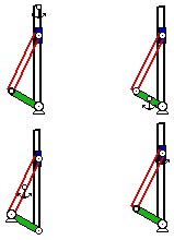
Inversions of the Slider-Crank

Click the figure above to activate the associated
video simulation file.
Software copyright © 2004 by The McGraw-Hill Companies, Inc. All rights reserved.
Info
The four links - crank (in green), coupler (in red), slider (in blue), and track (in black) - are successively fixed (shown with an anchor) in each of the inversion. In the slider-crank (shown in upper right corner), the slider block translates; in the lower left inversion, the slider block rotates; in the lower right inversion, the slider block is fixed; and in the upper right inversion, the slider block has complex motion.
Source
This Working Model file is adapted from Figure 2-13 on p.46 in Design of Machinery, 3rd ed. by Norton, R.L., McGraw-Hill, 2004.
Credits
This Working Model file was first developed by Fan (Michael) Mo.