Wishbone Suspensions

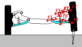
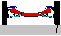
Click the figure above to activate the associated video simulation file.
Software copyright © 2004 by The McGraw-Hill Companies, Inc. All rights reserved.
Info
The wishbone suspension is a fourbar linkage. The upper control arm (in blue) and lower control arm (in light blue) connects the wheel assembly, to the frame (in red).
To simulate a car drives over a speed bump on one side, a position actuator is placed under the right wheel with its length changing.
The second simulation file shows the same suspension with reaction force shown on the spring, the upper control arm (a two-force member) and the lower control arm.
Source
This Working Model 2D file is adapted from Figure 3.19(a) on p.118 in Design of Machinery, 3rd ed. by Norton, R. L., McGraw-Hill, 2004.
It is also from Figure 1.1.4 on p. 6 in Computer-Aided Kinematics and Dynamics of Mechanical Systems, Volume I: Basic Methods, by Haug, E.J., published by Allyn and Bacon, 1989, from Figure 5.16-13 on p.175 in Kinematics and Dynamics of Planar Machinery by Paul, B. K., Prentice-Hall, 1979, from Figure 4.107 on P.225 and Figure 7.54 on p.445 in Engineering Mechanics-Statics, 4th ed., by Meriam, J.L. and., Kraige, L.G., John Wiley & Sons., 1997, from Figure 10.42 on p.546 in Engineering Mechanics-Dynamics, 2nd ed., by Bedford, A. and Fowler, W.L., Addison-Wesley, 1999, and from Figure P4.225 on p. 262 in Engineering Mechanics, Statics, 3rd ed. by McGill, D.J., and King, W.W., PWS Publishing Company, 1995.
Credits
This Working Model file was first developed by Fan (Michael) Mo.
