Automotive Differential
 Driving Straight Ahead vN4D File |
 Right Wheel Stationary vN4D File |
Click the figure above to activate the associated
video simulation file.

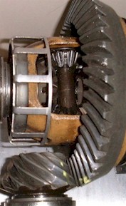
Rear Differentials of Volvo 740
Software copyright © 2004 by The McGraw-Hill Companies, Inc. All rights reserved.
Info
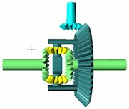
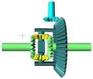
The input gear (in blue) is connected to the drive shaft. It drives the ring gear (in dark green, a large bevel gear). Note that the carrier (in dark green), where planetary gears (in yellow) are mounted, is rigidly connected to the ring gear. The planet gears drive the two side bevel gears and shafts (in light green.)
In the first simulation, the vehicle is moving straight ahead, and the two wheels are turning at the same speed. The ring gear and two side gears are turning at the same speed. Note that planet gears are not spinning.
In the second simulation, the right axle is stationary, as in the case when the right wheel is on a patch of ice and loses traction. The left shaft is then turning twice the normal speed, as it receives the entire power from the drive train. Note that planet gears are spinning.
For more information about the principle of differential gear train, click here.
Source
This Working Model file is adapted from Figure 9-53(a) on p.511 in Design of Machinery, 3rd ed. by Norton, R.L., McGraw-Hill, 2004.
It is also adapted from Figure P13-18 on p. 887 in Mechanical Engineering Design, 6th ed. by Shigley, J.E. and Mischke C.R., McGraw-Hill, 2001, from Figure 7.20 on p.448 in Mechanism Design: Analysis and Synthesis, 3rd ed. by Erdman, A.G. and Sandor, G.N., Prentice Hall, 1996, and from Figure 7.12 on p. 260 in Mechanisms and Dynamics of Machinery, 4th ed. by Mabie, H.H and Reinholtz, C.F., John Wiley & Sons, 1987, and also from Figure 505 on p. 455 in Kinematics of Machinery by Albert, C.D. and Rogers, F.S., John Wiley & Sons, Inc., 1931.
Credits
This Working Model file was first developed by Jie (Jeff) Yang. This photo was taken by Shih-Liang (Sid) Wang