Activity Diagram
l
Describes activities and flows
of data or decisions between activities
l
Provides a very broad view of
business processes
l
Breaks out the activities that
occur within a use case
l
Shows many different activities
that will be handled by lots of different symbols
l
Shows parallel threads
![]() Figure 6.1 An activity diagram
Figure 6.1 An activity diagram
l
When describing work flow
across many use cases
l
When analyzing a use case, and
before methods are assigned to symbols
l When dealing with multi-threaded applications
l
When modeling the function of a
system since activity diagram emphasize the flow of control among objects
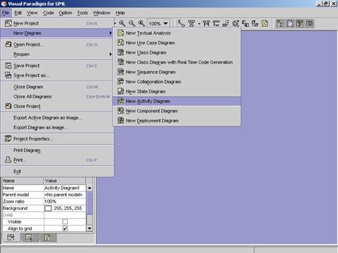
Method 1 �V Creating an activity diagram using the menu bar
1.
Click on File on the menu bar. The file menu appears.
2.
Click on New Diagram on the file menu. A cascading menu appears.
3.
Click on New Activity Diagram on the cascading menu. A blank new activity diagram
appears.
Method 2 �V Creating an activity diagram using the toolbar
1. Click on Create Activity Diagram
![]() on the toolbar. A blank new activity
diagram appears.
on the toolbar. A blank new activity
diagram appears.

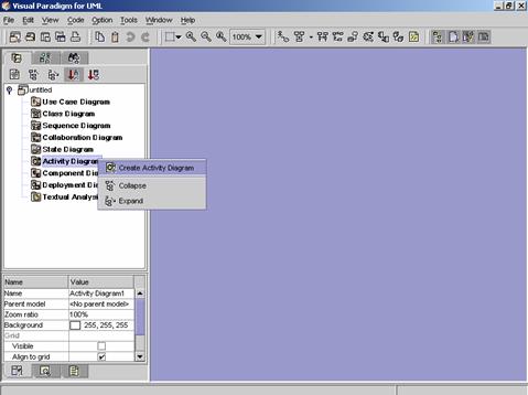
Method 3 �V Creating an activity diagram
using the Project Explorer
1.
Right click on Activity Diagram directory in the
Project Explorer. A pop-up menu appears.
2.
Click on Create Activity Diagram on the pop-up menu. A blank new activity diagram
appears.
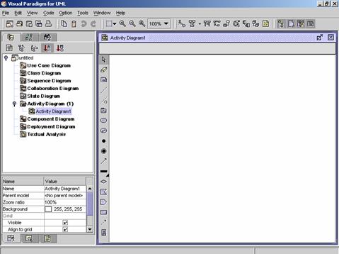
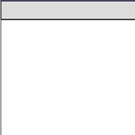
![]() Figure 6.2 A blank new activity diagram is
created.
Figure 6.2 A blank new activity diagram is
created.
|
|
Icon |
Notation |
Definition |
|
|
Note |
A note is used for comments additional explanation, specification and requirement in a diagram element or at a link in the diagram. It is not included in generated code. The contents of a note do not alter the meaning of the model to which it is attached. A note can contain any combination of text and graphics. It can also be used in defining a stereotype and entering a noted element. (adapted from UMLUG-purple) |
|
|
|
Anchor |
An anchor is used to line a diagram element and a note. |
|
|
|
Subsystem |
A subsystem groups diagram elements together. |
|
|
|
|
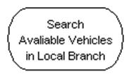
A state that represents the execution of an atomic action, mostly the invocation of an operation. |
|
|
|
Sub Activity |
An sub activity is the activity that will perform within a larger activity. |
|
|
|
|
A pseudo state to establish the start of the event into an actual state. |
|
|
|
|
A final state will signify when a state transition ends. |
|
|
|
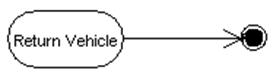
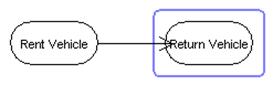
Transition |
A transition is a relationship between two states. This transition indicates that control is passed from the one state to another state once the work of the source state is completed. To emphasize functional flow of control, transitions can be labeled, and can contain parameters, guard conditions and action expressions. |
|
|
|
Horizontal Synchronization |
This merge branch bar symbol is also known as a ��Synchronization Bar��. It merges concurrent transitions to a single target. It splits a single transition into parallel transitions. |
|
|
|
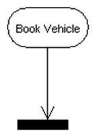
Vertical Synchronization |
This merge branch bar symbol is also known as a ��Synchronization Bar��. It merges concurrent transitions to a single target. It splits a single transition into parallel transitions. |
|
|
|
Decision Point |
Similar to flowchart, decision point is used to model the conditional flow of control. A decision is shown by labeling each output transition of a decision with a different guard condition. |
|
|
|
Signal Receipt |
A signal that may trigger a transition when received. |
|
|
|
Signal Sending |
A signal that may trigger a transition to another state in its state machine when sent. |
|
|
|
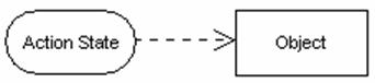
Object |
|
|
|
|
Object Flow |
A variety of
control flow that represents the relationship between an object and the
object, operation, or transition that creates it or uses it. (UMLUG-red) |
|
|
|
Swimlane |
Swimlane is a partition on interaction diagram for organizing responsibilities for activities. Each zone or lane represents the responsibilities of a particular class. To use swimlane, you must arrange activity diagrams into vertical zones separated by dashed lines. Transitions may cross boundaries. |
|
|
|
|
|
![]() Table 6.1 The Activity Diagram Palette of VPUML
Table 6.1 The Activity Diagram Palette of VPUML
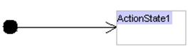
Creating
an Action State
Method
1 �V Creating an action state using the Activity Diagram Palette
1.
Click on the action state
button ![]() on the Activity Diagram Palette. Click on
the desired location on the diagram. A new action state appears.
on the Activity Diagram Palette. Click on
the desired location on the diagram. A new action state appears.
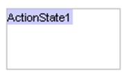
2. Rename the newly created action state. Press Ctrl + Enter to finish the operation.
|
|
è |
|
Method
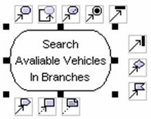
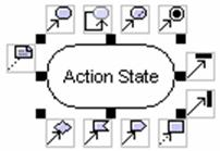
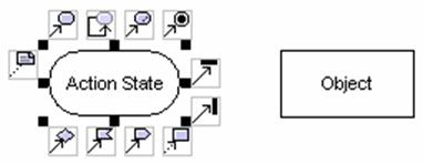
2 �V Creating an action state using the resource centric interface
Diagram elements that an action state can be created from, using the resource centric interface are:
l
![]()
l
Sub Activity ![]()
l
![]()
l
Horizontal Synchronization ![]()
l
Vertical Synchronization ![]()
l
Decision Point ![]()
l
Signal Receipt ![]()
l
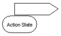
Signal Sending ![]()
l
Object ![]()
![]()
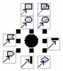
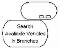
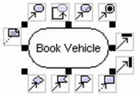
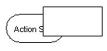
1.
Click on an existing diagram
element listed above on the diagram. Resource icons appear around the diagram
element.
2.
Press on the ![]() .
A new action state appears.
.
A new action state appears.
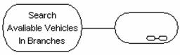
3. Drag the action state to the desired location. Release the mouse button.
|
|
è |
|
4. Rename the newly created action state. Press Ctrl + Enter to finish the operation.
|
|
è |
|
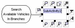
Method
1 �V Creating a sub activity using the Activity Diagram Palette
1.
Click on the sub activity
button ![]() on the Activity Diagram Palette. Click on
the desired location on the diagram. A new sub activity appears.
on the Activity Diagram Palette. Click on
the desired location on the diagram. A new sub activity appears.
2. Rename the newly created sub activity. Press Ctrl + Enter to finish the operation
|
|
è |
|
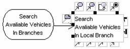
Method
2 �V Creating a sub activity using the resource centric interface
Diagram elements that a sub activity can be created from, using the resource centric interface are:
l
![]()
l
Sub Activity ![]()
l
Horizontal Synchronization ![]()
l
Vertical Synchronization ![]()
l
Signal Receipt ![]()
l
Signal Sending ![]()
l
Object Flow ![]()
1.
Click on an existing diagram
element listed above on the diagram. Resource icons appear around the diagram
element.
2.
Press on the sub activity
resource icon ![]() .
A new sub activity appears.
.
A new sub activity appears.
3. Drag the sub activity to the desired location. Release the mouse button.
|
|
è |
|
4. Rename the newly created sub activity. Press Ctrl + Enter to finish the operation.
|
|
è |
|

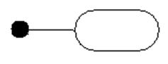
Create an Initial State
1.
Click on the initial state
button ![]() on the Activity Diagram Palette. Click on
the desired location on the diagram. A new initial state appears.
on the Activity Diagram Palette. Click on
the desired location on the diagram. A new initial state appears.
![]()
2. Rename the newly created initial state. Press Ctrl + Enter to finish the operation.
|
|
è |
|
Create a Final State
Method
1 �V Creating a final state using the Activity Diagram Palette
1.
Click on the final state button
![]() on the Activity Diagram Palette. Click on
the desired location on the diagram. A new final state appears.
on the Activity Diagram Palette. Click on
the desired location on the diagram. A new final state appears.
![]()
2. Rename the newly created final state. Press Ctrl + Enter to finish the operation.
|
|
è |
|
Method
2 �V Creating
a final state using the resource centric interface
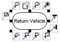
Diagram elements that a final state can be created from, using the resource centric interface are:
l
![]()
l
Sub Activity ![]()
l
Horizontal Synchronization ![]()
l
Vertical Synchronization ![]()
l
Decision Point ![]()
l
Signal Sending ![]()
l
Object ![]()

1.
Click on an existing diagram
element listed above on the diagram. Resource icons appear around the diagram
element.
2.
Press on the final state
resource icon ![]() .
A new final state appears.
.
A new final state appears.
3. Drag the final state to the desired location. Release the mouse button.
|
|
è |
|

4. Rename the newly created final state. Press Ctrl + Enter to finish the operation.
|
|
è |
|
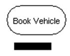
Method
1 �V Creating a horizontal synchronization using the Activity Diagram Palette
1.
Click on the horizontal
synchronization button ![]() on the Activity Diagram Palette. Click on
the desired location on the diagram. A new horizontal synchronization appears.
on the Activity Diagram Palette. Click on
the desired location on the diagram. A new horizontal synchronization appears.
![]()
2. Rename the newly created horizontal synchronization. Press Ctrl + Enter to finish the operation.
|
|
è |
|
Method
2 �V Creating
a horizontal synchronization using the resource centric interface
Diagram elements that a horizontal synchronization can be created from, using the resource centric interface are:
l
![]()
l
Sub Activity ![]()
l
Horizontal Synchronization ![]()
l
Vertical Synchronization ![]()
l
Decision Point ![]()
l
Signal Receipt ![]()
l
Signal Sending ![]()
l
Object ![]()
1.
Click on an existing diagram
element listed above on the diagram. Resource icons appear around the diagram
element.
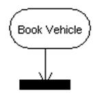
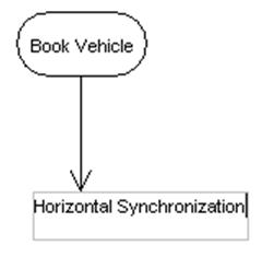
2.
Press on the horizontal
synchronization resource icon ![]() .
A new horizontal synchronization appears.
.
A new horizontal synchronization appears.
3. Drag the horizontal synchronization to the desired location. Release the mouse button.
|
|
è |
|
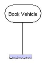
4. Rename the newly created horizontal synchronization. Press Ctrl + Enter to finish the operation.
|
|
è |
|
Method
1 �V Creating a vertical synchronization using the Activity Diagram Palette
1.
Click on the vertical
synchronization button ![]() on the Activity Diagram Palette. Click on
the desired location on the diagram. A new vertical synchronization appears.
on the Activity Diagram Palette. Click on
the desired location on the diagram. A new vertical synchronization appears.
![]()
2. Rename the newly created vertical synchronization. Press Ctrl + Enter to finish the operation.
|
|
è |
|
Method
2 �V Creating
a vertical synchronization using the resource centric interface
Diagram elements that a vertical synchronization can be created from, using the resource centric interface are:
l
![]()
l
Sub Activity ![]()
l
Horizontal Synchronization ![]()
l
Vertical Synchronization ![]()
l
Decision Point ![]()
l
Signal Receipt ![]()
l
Signal Sending ![]()
l
Object ![]()
1.
Click on an existing diagram
element listed above on the diagram. Resource icons appear around the diagram
element.
2.
Press on the vertical
synchronization resource icon ![]() .
A new vertical synchronization appears.
.
A new vertical synchronization appears.
3. Drag the vertical synchronization to the desired location. Release the mouse button.
|
|
è |
|
4. Rename the newly created vertical synchronization. Press Ctrl + Enter to finish the operation.
|
|
è |
|

Method
1 �V Creating a decision point using the Activity Diagram Palette
1.
Click on the decision point
button ![]() on the Activity Diagram Palette. Click on
the desired location on the diagram. A new decision point appears.
on the Activity Diagram Palette. Click on
the desired location on the diagram. A new decision point appears.
![]()
2. Rename the newly created decision point. Press Ctrl + Enter to finish the operation.
|
|
è |
|

Method
2 �V Creating
a decision point using the resource centric interface
Diagram elements that a decision point can be created from, using the resource centric interface are:
l
![]()
l
Sub Activity ![]()
l
Horizontal Synchronization ![]()
l
Vertical Synchronization ![]()
l
Decision Point ![]()
l
Signal Receipt ![]()
l
Signal Sending ![]()
l
Object ![]()
1.
Click on an existing diagram
element listed above on the diagram. Resource icons appear around the diagram
element.
2.
Press on the decision point resource
icon ![]() .
A new decision point appears.
.
A new decision point appears.
3. Drag the decision point to the desired location. Release the mouse button.
|
|
è |
|
4. Rename the newly created decision point. Press Ctrl + Enter to finish the operation.
|
|
è |
|
Method
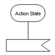
1 �V Creating a signal receipt using the Activity Diagram Palette
1.
Click on the signal receipt
button ![]() on the Activity Diagram Palette. Click on
the desired location on the diagram. A new signal receipt appears.
on the Activity Diagram Palette. Click on
the desired location on the diagram. A new signal receipt appears.
2. Rename the newly created signal receipt. Press Ctrl + Enter to finish the operation.
|
|
è |
|
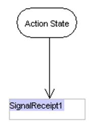
Method
2 �V Creating a signal receipt using the resource centric interface
Below is a list of diagram elements that can create signal receipt with transition using the resource centric interface:
l
![]()
l
Sub Activity ![]()
l
![]()
l
Horizontal Synchronization ![]()
l
Vertical Synchronization ![]()
l
Decision Point ![]()
l
Object ![]()
1.
Click on any existing diagram
elements listed above on the diagram. Resource icons appear around the diagram
element.
2.
Press on the signal receipt
resource icon ![]() .
A new signal receipt appears.
.
A new signal receipt appears.
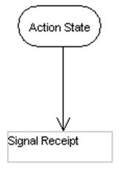
3. Drag the signal receipt to the desired location. Release the mouse button.
|
|
è |
|
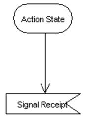
4. Rename the newly created signal receipt. Press Ctrl + Enter to finish the operation.
|
|
è |
|
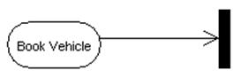
Method
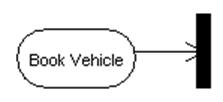
1 �V Creating a signal sending using the Activity Diagram Palette
1.
Click on the signal sending
button ![]() on the Activity Diagram Palette. Click on
the desired location on the diagram. A new signal sending appears.
on the Activity Diagram Palette. Click on
the desired location on the diagram. A new signal sending appears.
2. Rename the newly created signal sending. Press Ctrl + Enter to finish the operation.
![]()
Method
2 �V Creating a signal receipt using the resource centric interface
Diagram elements that signal receipt can be created from, using the resource centric interface are:
l
![]()
l
Sub Activity ![]()
l
![]()
l
Horizontal Synchronization ![]()
l
Vertical Synchronization ![]()
l
Decision Point ![]()
l
Signal Receipt ![]()
l
Object ![]()
1.
Click on any of the existing
diagram elements listed above on the diagram. Resource icons appear around the
diagram element.
2.
Press on the signal sending
resource icon ![]() .
A new signal sending appears.
.
A new signal sending appears.
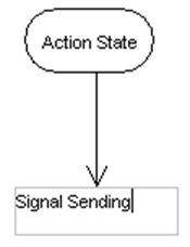
3. Drag the signal sending to the desired location. Release the mouse button.
|
|
è |
|
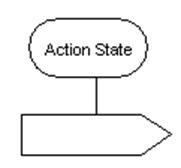
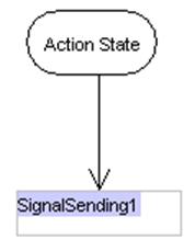
4. Rename the newly created signal sending. Press Ctrl + Enter to finish the operation.
|
|
è |
|
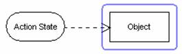
Method
1 �V Creating an object using the Activity Diagram Palette
1.
Click on the object button ![]() on the Activity Diagram Palette. Click on
the desired location on the diagram. A new object is created.
on the Activity Diagram Palette. Click on
the desired location on the diagram. A new object is created.
2. Rename the newly created object. Press Ctrl + Enter to finish the operation.
|
|
è |
|
Method
2 �V Creating an object using the resource centric interface
Below is a list of diagram elements that can create object with transition using the resource centric interface:
l
![]()
l
Sub Activity ![]()
l
![]()
l
Horizontal Synchronization ![]()
l
Vertical Synchronization ![]()
l
Decision Point ![]()
l
Signal Receipt ![]()
l
Signal Sending ![]()
l
Object ![]()
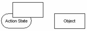
1.
Click on an existing diagram
element listed above on the diagram. Resource icons appear around the diagram
element.
2.
Press on the object resource icon ![]() .
A new object appears.
.
A new object appears.
3. Drag the object to the desired location. Release the mouse button.
|
|
è |
|
4. Rename the newly created object. Press Ctrl + Enter to finish the operation.
|
|
è |
|
Method
1 �V Creating a transition using the activity diagram palette
You can create transition between diagram elements listed below in the activity diagram.
l
![]()
l
Sub Activity ![]()
l
![]() (Note: Cannot be the target diagram
element)
(Note: Cannot be the target diagram
element)
l
![]() (Note: Cannot be the source diagram
element)
(Note: Cannot be the source diagram
element)
l
Horizontal Synchronization ![]()
l
Vertical Synchronization ![]()
l
Decision Point ![]()
l
Signal Receipt ![]()
l
Signal Sending ![]()
l
Object ![]()
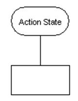
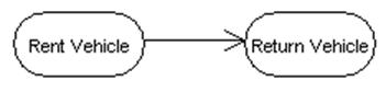
1.
Click on the transition button ![]() on the Activity Diagram Palette. Drag
from the source diagram element to the target diagram element.
on the Activity Diagram Palette. Drag
from the source diagram element to the target diagram element.
|
|
è |
|
2. Release the mouse button. A new transition is created between the diagram elements.
Method
2 �V Creating a transition using the resource centric interface
Diagram elements that a transition can be created from, using the resource centric interface:
l
![]()
l
Sub Activity ![]()
l
![]()
l
Horizontal Synchronization ![]()
l
Vertical Synchronization ![]()
l
Decision Point ![]()
l
Signal Receipt ![]()
l
Signal Sending ![]()
l
Object ![]()
1.
Click on an existing diagram
element listed above on the diagram. Resource icons appear around the diagram
element.
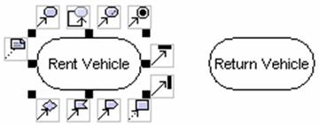
2.
Press on the any resource icon
with transition (![]() ,
,![]() ,
,![]() ,
�K). A new diagram element appears. (Note: You must choose the resource
icon correspondent to the target diagram element)
,
�K). A new diagram element appears. (Note: You must choose the resource
icon correspondent to the target diagram element)
3. Drag the new diagram element to the target diagram element. The target diagram element is selected.
|
|
è |
|
4.
Release the mouse button. The
transition is created between the diagram elements.
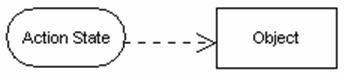
Method
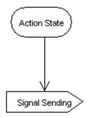
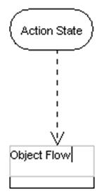
1 �V Creating an object flow using the activity diagram palette
You can create transition between diagram elements listed below in the activity diagram.
l
![]()
l
Sub Activity ![]()
l
![]() (Note: Cannot be the target diagram
element)
(Note: Cannot be the target diagram
element)
l
![]() (Note: Cannot be the source diagram
element)
(Note: Cannot be the source diagram
element)
l
Horizontal Synchronization ![]()
l
Vertical Synchronization ![]()
l
Decision Point ![]()
l
Signal Receipt ![]()
l
Signal Sending ![]()
l
Object ![]()
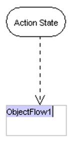
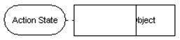
3.
Click on the object flow button
![]() on the Activity Diagram Palette. Drag
from the source diagram element to the target diagram element.
on the Activity Diagram Palette. Drag
from the source diagram element to the target diagram element.
|
|
è |
|
4. Release the mouse button. A new object flow is created between the diagram elements.
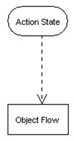
Method
2 �V Creating an object flow using the resource centric interface
Diagram elements that an object flows can be created from, using the resource centric interface:
l
![]()
l
Sub Activity ![]()
l
![]()
l
Horizontal Synchronization ![]()
l
Vertical Synchronization ![]()
l
Decision Point ![]()
l
Signal Receipt ![]()
l
Signal Sending ![]()
l
Object ![]()
5.
Click on an existing diagram
element listed above on the diagram. Resource icons appear around the diagram
element.
6.
Press on the object flow to
object resource icon![]() .
A new diagram element appears.
.
A new diagram element appears.
7. Drag the new diagram element to the target diagram element. The target diagram element is selected.
|
|
è |
|
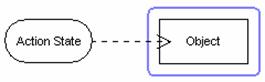
8.
Release the mouse button. The
object flow is created between the diagram elements.
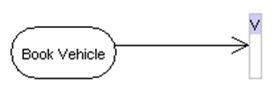
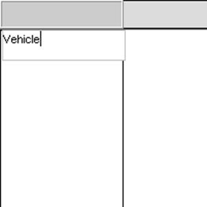
Creating a Swimlane
1.
Click on the swimlane button ![]() on the Activity Diagram Palette. Click on
the desired location on the diagram. A new swimlane appears.
on the Activity Diagram Palette. Click on
the desired location on the diagram. A new swimlane appears.
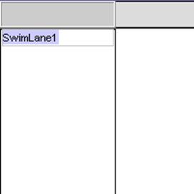
2. Rename the newly created object. Press Ctrl + Enter to finish the operation.
ê
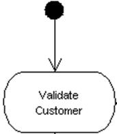
1.
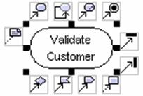
Click on the
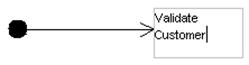
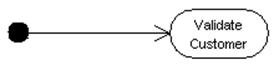
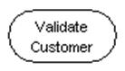
![]()
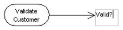
2. Click on the initial state. The Resource icons appear around the initial state. Click on the Transition -> Action resource icon. A new action state appears. Drag the action state to the desired location. Rename it as ��Validate Customer��.
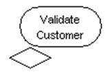
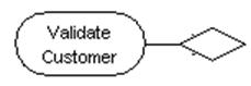
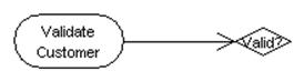
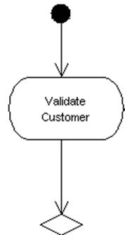
3. Click on the action state. Resource icons appear around the action state. Click on the Transition -> Decision. A new decision point with a transition appears. Drag the decision point to the desired location.
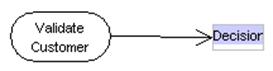
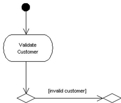
4. Click on the decision point. Resource icons appear around the decision point. Click on the Transition -> Decision resource icon. A new decision point with a transition appears. Drag the decision point to the desired location. Double click on the transition that between the decision points. A text box appears. Rename the transition as ��[invalid customer]��.
5. Click on the lastly created decision point. Resource icons appear around the diagram element. Click on the Transition -> Action resource icon. A new action state with a transition appears. Rename the new action state as ��Register Customer��. Rename the transition between the new action state and the decision point as ��[register]��.
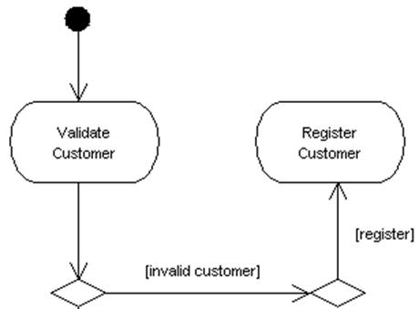
6.
Click on the lastly created
decision point. Resource icons appear around the diagram element. Click on the Transition ->
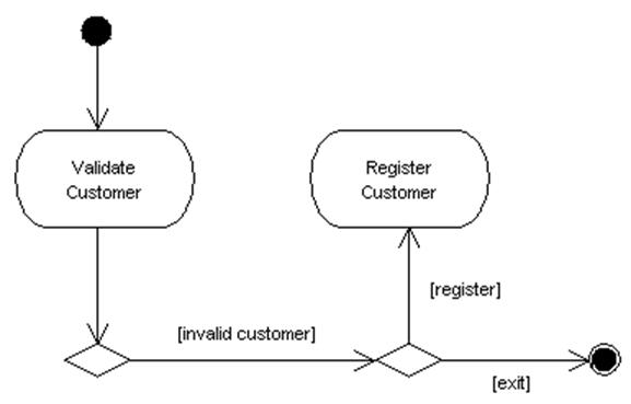
7. Click on the Initial Sate button on the Activity Diagram Palette. Click on the desired location on the diagram. A new initial state appears. Click on the new initial state. Resource icons appear around the initial state. Click on the Transition -> Action. A new action state appears. Drag the new action state to the Register Customer action state. A transition is created between the new initial state and the Register Customer action state.
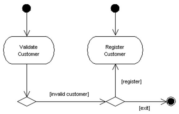
Draw the diagram below according to the guidelines given in this chapter.
![]() Figure 6.3 An activity diagram
Figure 6.3 An activity diagram