Class Diagram
A class diagram describes the static
structure of the symbols in your new system. It is a graphic presentation of
the static view that shows a collection of declarative (static) model elements,
such as classes, types, and their contents and relationships. Classes are
arranged in hierarchies sharing common structure and behavior, and are
associated with other classes
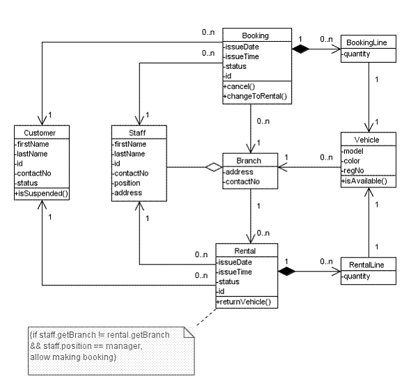
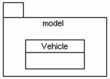
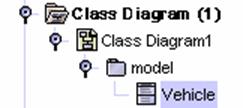
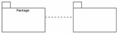
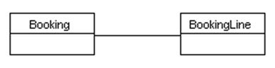
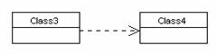
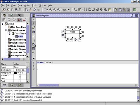
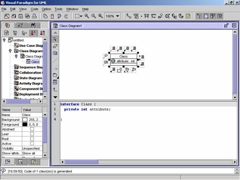
![]() Figure 9.1 A class diagram.
Figure 9.1 A class diagram.
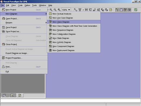
Method 1 �V Creating a blank new class diagram using the main menu
1.
Click on File on the main menu. The file menu appears.
2.
Click on New Diagram on the file menu. A cascading menu appears.
3.
Click on New Class Diagram on the cascading menu. A blank new class diagram
appears.
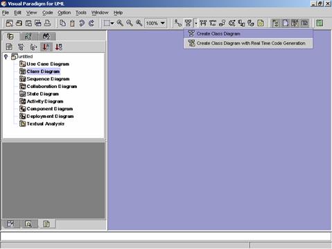
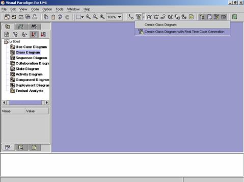
Method 2 �V Creating a blank new class diagram using the toolbar
1. Click on Create Class Diagram
![]() on the toolbar. A pop-up menu appears.
on the toolbar. A pop-up menu appears.
2. Click on Create Class Diagram
on the pop-up menu. A blank new class diagram appears.
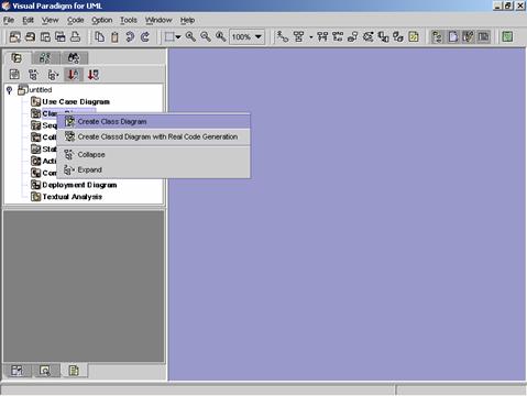
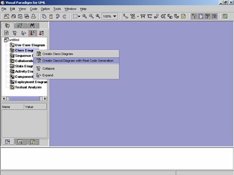
Method 3 �V Creating a blank new class
diagram using the Project Explorer
1.
Right click on the Class Diagram directory in the Project
Explorer. A pop-up menu appears.
2.
Click on Create Class Diagram on the pop-up menu. A blank new class diagram
appears.
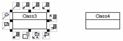
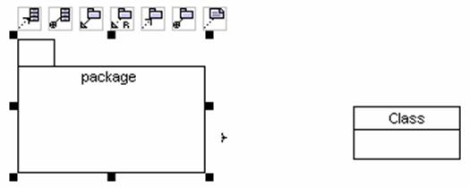
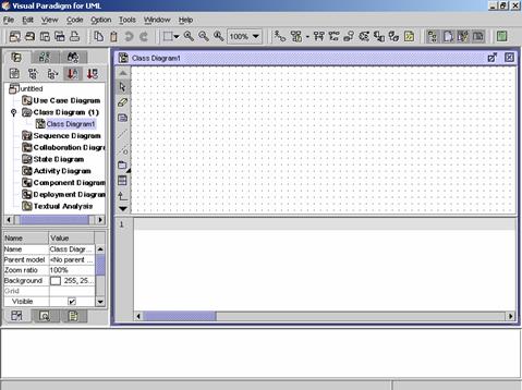
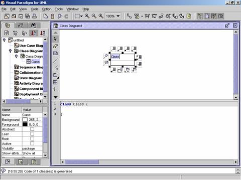
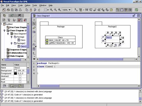
![]() Figure 9.2 A blank new class diagram is created.
Figure 9.2 A blank new class diagram is created.
|
|
Icon |
Notation |
Definition |
|
|
Note |
A note is used for comments additional explanation,
specification and requirement in a diagram element or at a link in the
diagram. It is not included in
generated code. The contents of a
note do not alter the meaning of the model to which it is attached. A note
can contain any combination of text and graphics. It can also be used in
defining a stereotype and entering a noted element. (adapted from
UMLUG-purple) |
|
|
|
Anchor |
An anchor is used to line a diagram element and a
note. |
|
|
|
Constraint |
|
|
|
|
Model |
|
|
|
|
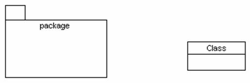
Package |
A package is a mechanism for organizing elements
into groups. It is used in the
Use Case, Class, and Component diagrams.
Packages may be nested within other packages. A package may contain
both subordinate packages and ordinary model elements. The entire system description can be
thought of as a single high-level subsystem package with everything else in
it |
|
|
|
Subsystem |
A subsystem groups diagram elements together. |
|
|
|
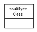
Class |
A Class is a description for a set of objects that
shares the same attributes, and has similar operations, relationships,
behaviors and semantics. |
|
|
|
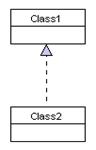
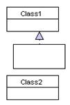
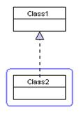
Generalization |
Generalization is a relationship between a general
element and a more specific kind of that element. It means that the more
specific element can be used whenever the general element appears. This
relation is also known as specialization or inheritance link. |
|
|
|
Usage |
Usage is a dependency situation in which one element
(the client) requires the presence of another element (the supplier) for its
correct functioning or implementation. |
|
|
|
Realization |
Realization is the relationship between a
specialization and its implementation.
It is an indication of the inheritance of behavior without the
inheritance of structure. One
classifier specifies a contract such that another classifier guarantees to
carry out
Realization is used in two places: one is between interfaces
and the classes that realize them, and the other is between use cases and the
collaboration that realize them. |
|
|
|
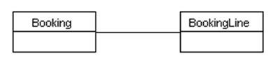
Association |
Association is represented by drawing a line between
classes. Associations represent
structural relationships between classes and can be named to facilitate model
understanding. If two classes are
associated, you can navigate from an object of one class to an object of the
class. |
|
|
|
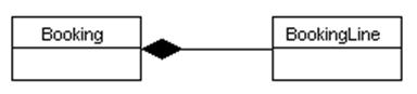
Aggregation |
Aggregation is a special kind of association in
which one class represents as the larger class that consists of a smaller
class. It has the meaning of
��has-a�� relationship. |
|
|
|
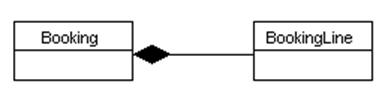
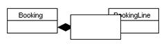
Composition |
Composition is a strong form of aggregation
association. It has strong ownership and coincident lifetime of parts by the
whole. A part may belong to only one composite. Parts with non-fixed
multiplicity may be created after the composite itself. But once created,
they live and die with it (that is, they share lifetimes). Such parts can
also be explicitly removed before the death of the composite. |
|
|
|
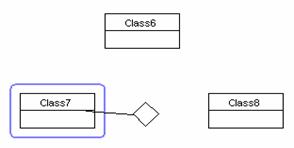
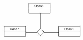
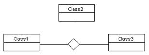
N-ary Association |
N-ary associations are
associations that connect more than two classes. Each instance of the association is an
n-tuple of values from the respective classes. There are several characteristics for
n-ary associations, which are: (i)
Multiplicity for ternary associations can be specifie;
(ii) The name of the association (if any) is shown near the diamond; (iii)
Role adornments can appear on each path as with a binary association; (iv)
The multiplicity on a role represents the potential number of instance tuples in the association when the other N-1 values are
fixed. Indeed, binary association
is a special case that it has its own notation. |
|
|
|
Association Class |
Association class is an association that is also a
class. It has both association
and class properties. It can have
attributes, operations and even other associations. It usually helps to further define a
many-to-many relationship. |
|
|
|
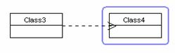
Dependency |
The dependency link is a semantic relationship
between the two elements. It indicates that when a change occurs in one
element, there may be a change necessary to the other element. A dependency link can include label
and stereotype can be set. |
|
|
|
Abstraction |
|
|
|
|
Binding Dependency |
|
|
|
|
Permission |
|
|
|
|
Collaboration |
|
|
|
|
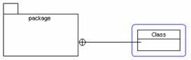
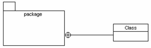
Containment |
|
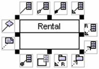
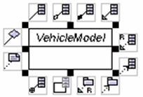
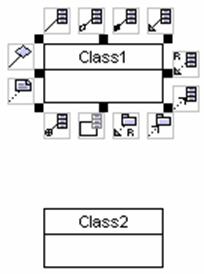
![]() Figure 9.3 The Class Diagram Palette of VPUML
Figure 9.3 The Class Diagram Palette of VPUML
Method 1 �V Creating a class using the Class Diagram Palette
1. Click on the Class
button ![]() on the Class Diagram Palette. Click on
the desired location on the diagram. A new class appears.
on the Class Diagram Palette. Click on
the desired location on the diagram. A new class appears.
2. Rename the newly created class. Press Ctrl + Enter to finish the operation.
|
|
è |
|
Method 2 �V Creating a class using the resource centric interface
Diagram elements that a class can be created from, using the resource centric interface are:
l Class ![]()
l Package ![]()
l N-ary Association ![]()
1. Click on an existing diagram element listed above on the diagram.
Resource icons appear around the diagram element.
2. Press one of the resource icons with Class (![]() ,
, ![]() ,
,
![]() ,
...). A new class appears.
,
...). A new class appears.
3. Drag the new class to the desired location. Release the mouse button.
|
|
è |
|
4. Rename the newly created class. Press Ctrl + Enter to finish the operation.
|
|
è |
|
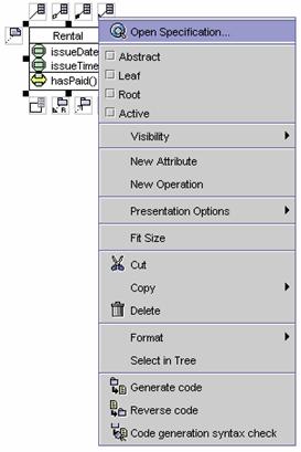
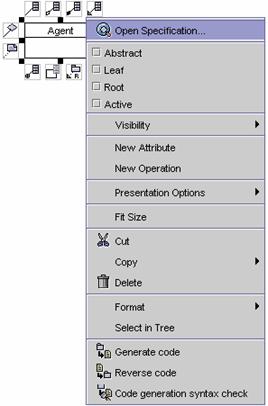
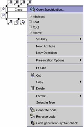
Method 1 �V Adding an attribute to a class using the pop-up menu
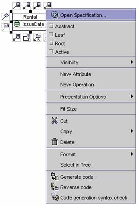
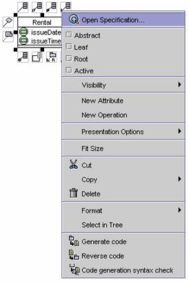
1. Right click on the class. A pop-up menu appears.
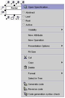
2. Click on New
attribute on the pop-up menu. A new attribute
is added to the class.
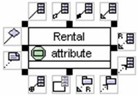
3. Double click on the newly created attribute.
|
|
è |
|
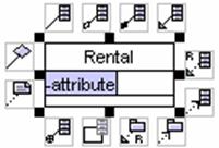
4. Press Ctrl
+ Enter to finish the operation.
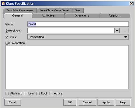
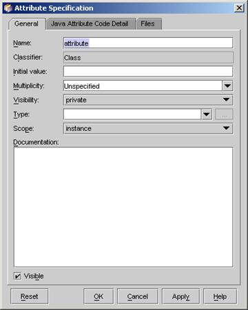
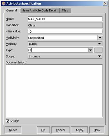
Method 2 �V Adding an attribute to a class using the specification
dialog box
1. Right click on an existing class on the diagram. A pop-up menu
appears.
2. Click on Open
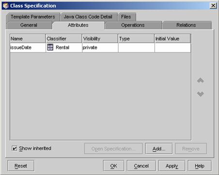
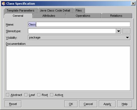
specification on the pop-up menu. The class specification dialog box appears.

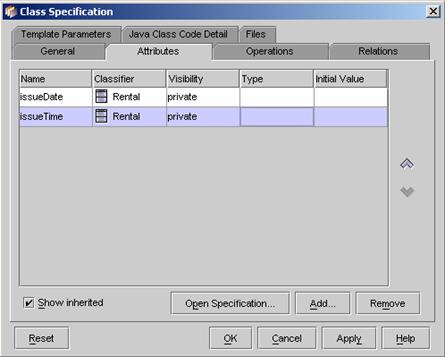
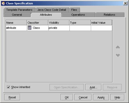
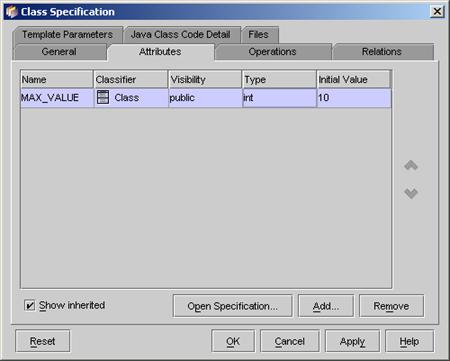
3. Click on the Attributes tab
in the specification dialog box. The attribute table appears.
4. Right click on the attribute table. A pop-up menu appears.
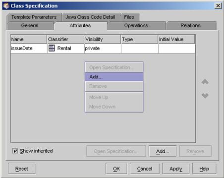
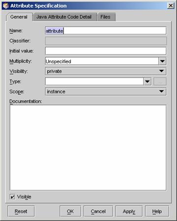
5. Click on Add�K on the pop-up
menu. The Attribute Specification
dialog appears. In the General tab, edit
attribute properties �V Name, Initial
Value, Multiplicity, Visibility, Type, Scope, Documentation and Visible.
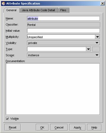
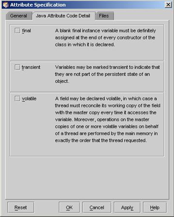
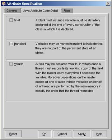
6. Click on the Java Attribute Code Detail in the dialog. Set the final, transient, and volatile properties for the attribute.
7. Click on OK button to
close the Attribute Specification
dialog box. The attribute is added to the class. Click on OK button to close the Class Specification.
8. The new attribute is added to the class.
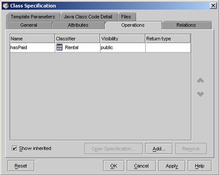
Method 1 �V Adding an operation to a class using the pop-up menu
1. Right click on an existing class on the diagram. A pop-up menu
appears.
2. Click on New
operation in the pop-up menu. A new operation is added.
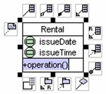
3. Rename the operation name. Press Ctrl + Enter to finish the operation.
|
|
è |
|
Method 2 �V Adding an operation in a class using the specification
dialog box
1. Right click on an existing class. A pop-up menu appears.
2. Click on Open
Specification in the pop-up menu. The class
specification dialog box appears.
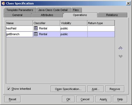
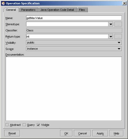
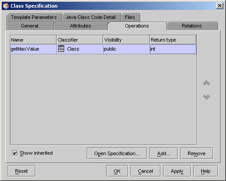
3. Click on the Operation
tab. The operation table appears.
4. Right click on the operation table. A pop-up menu appears.
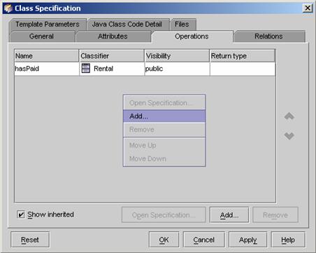
5. Click on Add... button on the popup menu. The Operation
Specification dialog appears. In the General
tab, edit the properties �V Name,
Stereotype, Return Type, Visibility, Scope, Documentation, Abstract, Query and
Visible.

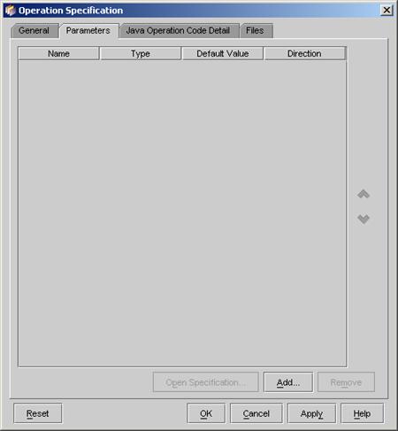
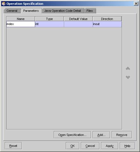
6. Click on the Parameter tab
in the Operation Specification
dialog.
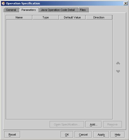
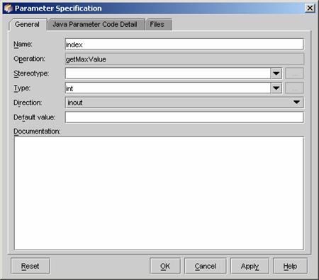
7. To add parameter to the operation, click the Add�K button in the dialog. The Parameter
Specification dialog appears. Edit the parameter properties �V Name, Stereotype, Type, Direction, Default
Value and Documentation.
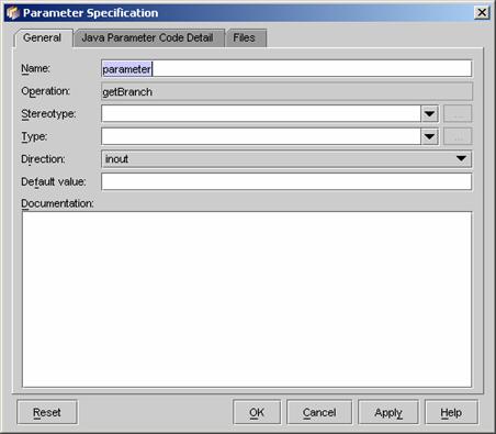
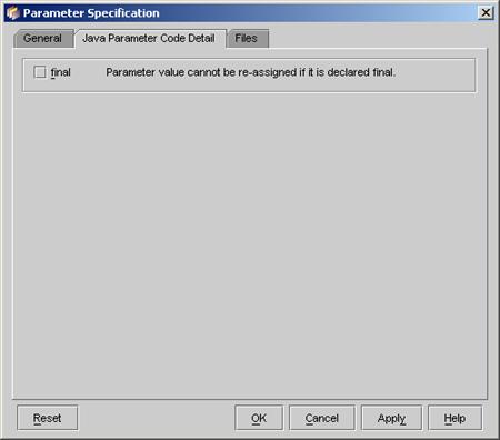
8. Click the Java Parameter Code Detail tab in the Parameter Specification dialog. Edit the final properties for the parameter.
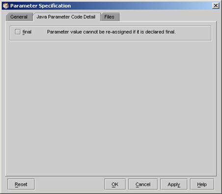
9. Click on OK to close the Parameter Specification dialog. The new parameter is added to the operation.

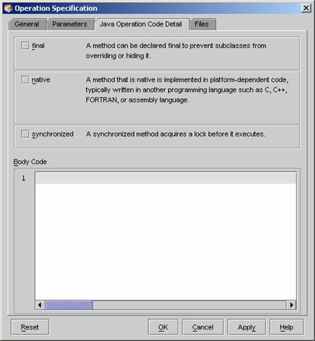
10. Click the Java Operation Code Detail in the Operation Speciation dialog. Edit the properties - final, native and synchronized for the operation.

11. Click OK button to close the Operation Specification dialog. The new operation is added to the class.
12. Click OK button to close the Class Specification dialog.
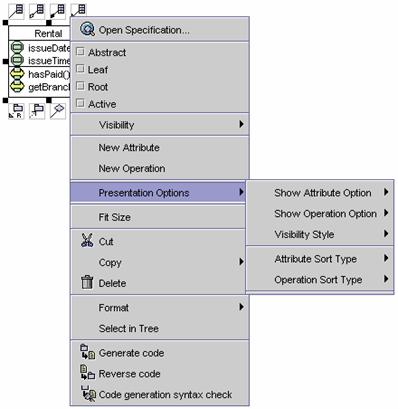
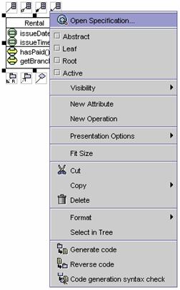
1. Right click on an existing class. A pop-up menu appears.
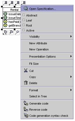
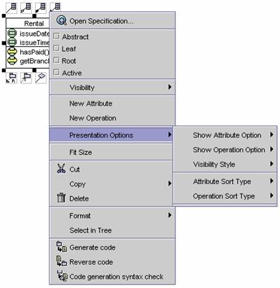
2. Click on Presentation Options in the popup menu. A cascading menu appears.
3. Click on Attribute Sort Type in the popup menu. A cascading menu appears.
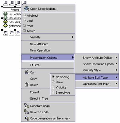
4. Choose one of the sorting types in the cascading menu. The attributes of the class will be sorted.
5. Right click on the class again. A pop-up menu appears.
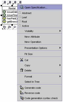
6. Click on Presentation Options in the popup menu. A cascading menu appears.
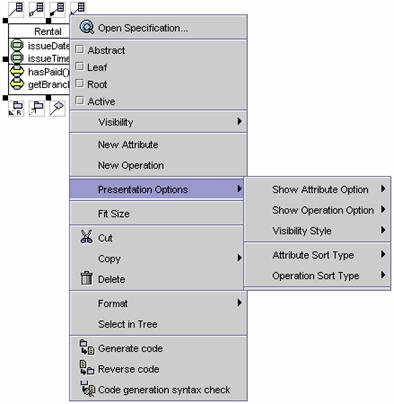
7. Click on Operation Sort Type in the popup menu. A cascading menu appears.
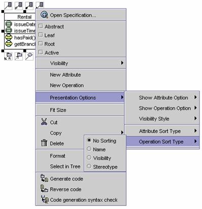
8. Choose one of the sorting types in the cascading menu. The operations of the class will be sorted.
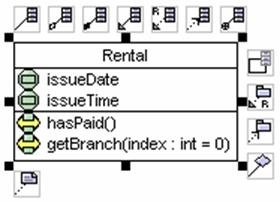
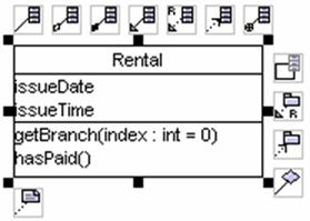
By default, the visibility style is set to icon style. The visibility style for a class can be changed.
1. Right click on an existing class. A pop-up menu appears.
2. Click on Presentation Options on the pop-up menu. A cascading menu appears.
3. Click on Visibility Style on the pop-up menu. A cascading menu appears. Check the UML Style option.
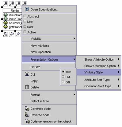
4. The visibility style of the class is set to UML style.
5. To disable the visibility, check the Off checkbox. The visibility is disabled.
1. Right click on an existing class. A pop-up menu appears.
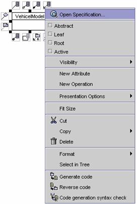
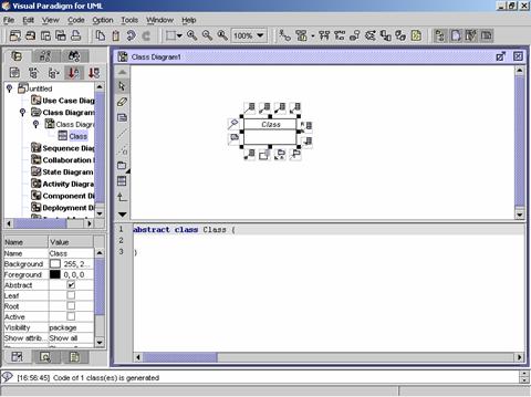
2. Check the Abstract Class option on the pop-up menu. The class is set to abstract class.
1. Right click on an existing class. A pop-up menu appears.
2. Check on the Action
checkbox on the pop-up menu. The class is set to active.
1. Right click on an existing class. A pop-up menu appears.
2. Click on Open
Specification on the pop-up menu. The specification dialog box appears.
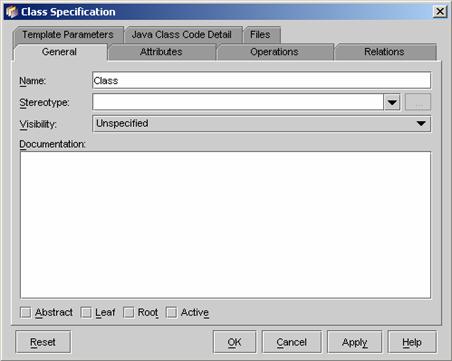
3. Click on the General
tab. Click on the Stereotype pull-down box and select one of the
stereotypes (Interface, Entity, Control, Boundary, or
define a new stereotype by typing the stereotype name in the pull-down box).
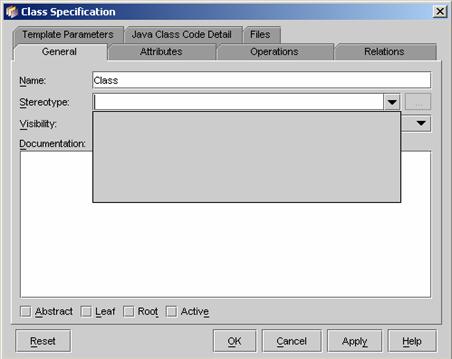
4. Click on OK
to close the specification dialog box. The shape of the class will be changed.
Interface
Entity
Control
Boundary
User define
Method 1 �V Creating a package using the Class Diagram Palette
1. Click on the Package
button ![]() on the Class Diagram Palette. Click on
the desired location on the diagram. A new package appears.
on the Class Diagram Palette. Click on
the desired location on the diagram. A new package appears.
2. Rename the newly created package. Press Ctrl + Enter to finish the operation.
|
|
è |
|
3. Create a class in the package. Then the package contains the class.
4. The project tree in the Project Explorer will show the hierarchy of
the packages.
Method 2 �V Creating a package using the resource centric interface
Diagram elements that a package can be created from, using the resource centric interface are:
l Class ![]()
l Package ![]()

5. Click on an existing diagram element listed above on the diagram.
Resource icons appear around the diagram element.
6. Press one of the resource icons with Class (![]() ,
,![]() ,
...). A new class appears.
,
...). A new class appears.
7. Drag the new package to the desired location. Release the mouse button.
|
|
è |
|
8. Rename the newly created package. Press Ctrl + Enter to finish the operation.
|
|
è |
|
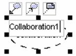
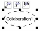
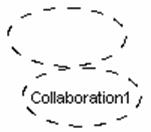
Method 1 �V Creating a collaboration using the Class Diagram Palette
1. Click on the Collaboration
button ![]() on the Class Diagram Palette. Click on
the desired location on the diagram. A new collaboration appears.
on the Class Diagram Palette. Click on
the desired location on the diagram. A new collaboration appears.
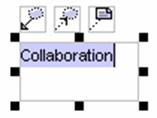
2. Rename the newly created collaboration. Press Ctrl + Enter to finish the operation.
|
|
è |
|
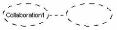
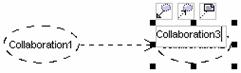
Method 2 �V Creating a collaboration using the resource centric
interface
Collaboration can be created
from an existing collaboration ![]() ,
using the resource centric interface.
,
using the resource centric interface.
1. Click on a collaboration listed above on the diagram. Resource icons
appear around the collaboration.

2. Press one of the resource icons with collaboration. A new collaboration
appears.
3. Drag the new collaboration to the desired location. Release the mouse button.
|
|
è |
|
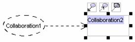
4. Rename the newly created collaboration. Press Ctrl + Enter to finish the operation.
|
|
è |
|
A constraint can be created between diagram elements.
1. Click on the Constraint
button ![]() on the Class Diagram Palette. Drag from
the source diagram element to the target diagram element.
on the Class Diagram Palette. Drag from
the source diagram element to the target diagram element.
|
|
è |
|
2. Rename the newly created constraint. Press Ctrl + Enter to finish the operation.
|
|
è |
|

Method 1 �V Creating an association link using the Class Diagram
Palette
An association can be created between
l A class ![]() ,
,
l An Association Class ![]() ,
and
,
and
l A N-ary association![]() .
.
3. Click on the Association
button ![]() on the Class Diagram Palette. Drag from
the source diagram element to the target diagram element.
on the Class Diagram Palette. Drag from
the source diagram element to the target diagram element.
|
|
è |
|
4. Release the mouse button. A new association is created between the diagram elements.
Method 2 �V Creating association using the resource centric interface
Diagram elements that an association link can be created from, using the resource centric interface are:
l A class ![]() ,
,
l An association class ![]() ,
or
,
or
l An N-ary association![]() .
.
1. Click on an existing diagram element listed above on the diagram.
Resource icons appear around the diagram element.
2. Press on the Association
-> Class button. A new class appears.
3. Drag the new class to the target diagram element. The target diagram element is selected.
|
|
è |
|
4. Release the mouse button. The association link is created between
the diagram elements.
Creating an Aggregation Relationship Link
Method 1 �V Creating an aggregation relationship link using the Class
Diagram Palette
An aggregation relationship link can be created between classes.

1. Click on the Aggregation
button ![]() on the Class Diagram Palette. Drag from a
class to the other class.
on the Class Diagram Palette. Drag from a
class to the other class.
|
|
è |
|
2. Release the mouse button. A new aggregation relationship link is created between the classes.
Method 2 �V Creating an aggregation relationship using the resource
centric interface
1. Click on an existing class. Resource icons appear the class.
2. Press on the Aggregation
-> class ![]() resource icon. A new class appears.
resource icon. A new class appears.
3. Drag the new class to the target class. The new class disappears. The target class is selected.
|
|
è |
|
4. Release the mouse button. The aggregation relationship link is
created between the classes.
Method 3 �V Creating an aggregation relationship link using an existing
association relationship link
You can change an existing
association relationship link to an aggregation relationship link.
1. Right click on an existing association. A pop-up menu appears.
2. Click Role A / Role B on the popup menu. A cascading menu appears.
3. Click Aggregation Kind on the cascading menu. A list of aggregation kinds appears.

4. Click on Aggregation on
the pop-up menu. The association relationship is changed to an aggregation
relationship link.
Method 1 �V Creating a composition relationship link using the Class
Diagram Palette
A composition relationship link can be created between classes.
1. Click on the Composition
button ![]() on the Class Diagram Palette. Drag from a
class to the other class.
on the Class Diagram Palette. Drag from a
class to the other class.
|
|
è |
|
2. Release the mouse button. A new composition relationship link is created between the classes.
Method 2 �V Creating a composition relationship link using the resource
centric interface
1. Click on an existing class in the diagram. Resource icons appear the
class.
2. Press on the Composition
-> Class ![]() .
A new class appears.
.
A new class appears.
3. Drag the new class to the target class. The new class disappears. The target class is selected.
|
|
è |
|

4. Release the mouse button. The composition relationship link is
created between the classes.
Method 3 �V Creating a composition relationship link using an existing
association relationship link
An existing association
relationship link can be changed to a composition relationship link.
1. Right click on an existing association link. A pop-up menu appears.
2. Click on Role A / Role B on the popup menu. A cascading menu appears.
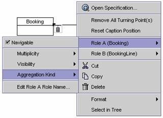
3. Click on Aggregation Kind in the cascading menu. A list of aggregation kinds appears.
4. Click on Composition
on the pop-up menu. The association relationship link is then changed to a
composition relationship link.
Method 1 �V Defining
association roles using the pop-up menu
1. Right click on an existing association. A popup menu appears.
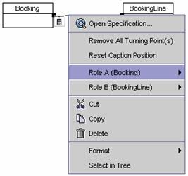
2. Click on Role A / Role B on the popup menu. A cascading menu appears.
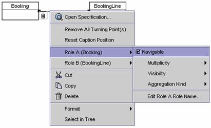
3. To edit if the role is navigable or not, click on the Navigable check box. The navigation between the elements is changed

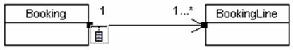
4. To edit the multiplicity of a role, right click on the association. A popup menu appears. Click on Role A / Role B on the popup menu. A cascading menu appears.
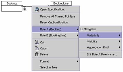
5. Click on Multiplicity on the cascading menu. A list of multiplicities appears.
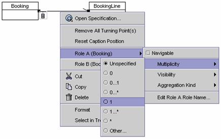
6. Choose one of the multiplicities. The multiplicity of the role is
set.
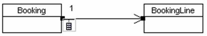
7. Use the same way to set the multiplicity of the other role.
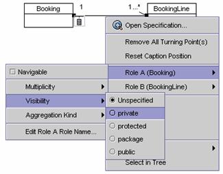
8. To edit the visibility of the role, right click on the association. A popup menu appears. Click on Role A / Role B. A cascading menu appears.
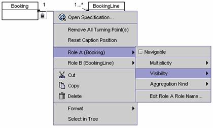
9. Click on Visibility on
the cascading menu. A list of visibilities appears. Choose one of the
visibilities.
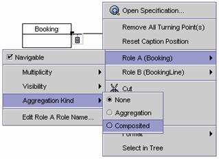
10. To edit the aggregation kind, right click on the association. A popup menu appears. Click on Role A / Role B. A cascading menu appears.
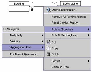
11. Click on Aggregation Kind on the cascading menu. A list of aggregation types appears.
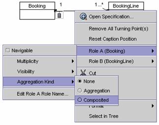
12. Choose one of the aggregation kinds. The aggregation type of the role is changed.
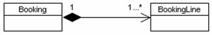
13. To edit a role name, right click on the association. A popup menu appears. Click Role A / Role B on the popup menu. A cascading menu appears.
14. Click Edit Role A/B Role Name on the cascading menu. An input dialog appears.

15.
Click on the OK button to
finish the operation.
Method 2 �V Defining
association roles using Association Specification dialog
1. Right click on the association. A popup menu appears.
2. Click Open Specification�K on the popup menu. The Association Specification dialog appears.
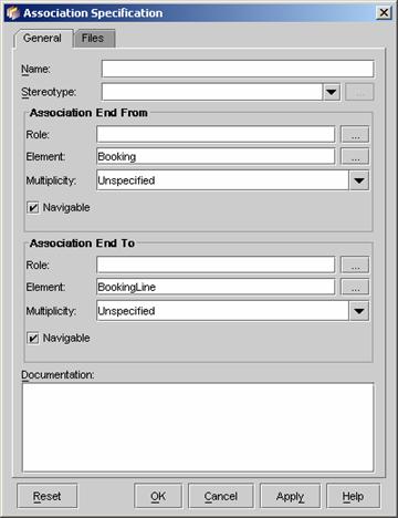
3. Edit the Role name, Multiplicity and Navigable properties of the
roles. Or click on the ![]() button near the Role text field. The Association
End Specification dialog appears. Edit the properties of the role.
button near the Role text field. The Association
End Specification dialog appears. Edit the properties of the role.
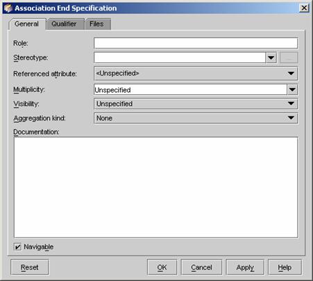
4. Click on the Qualifier tab on the Association End Specification dialog.
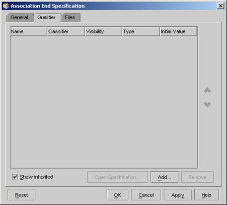
5. Click the Add�K button on the Association End Specification dialog. The Attribute Specification dialog appears. (See Adding an Attribute Section)
6. Click on the OK button on the Attribute Specification dialog. The new attribute is added as a qualifier.
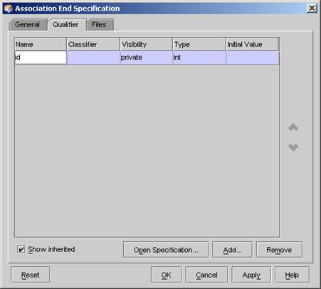
7. Click OK button on the Association End Specification dialog.
Method 1 �V Creating a generalization relationship link using the Class
Diagram Palette
A generalization relationship link can be created between:
l A class ![]() and a class
and a class ![]() ,
or
,
or
l A package ![]() and a package
and a package ![]() .
.

1. Click on the Generalization
button ![]() on the Class Diagram Palette. Drag from
the source diagram element to the target diagram element.
on the Class Diagram Palette. Drag from
the source diagram element to the target diagram element.
|
|
è |
|
2. Release the mouse button. A new generalization relationship link is created between the diagram elements.
Method 2 �V Creating a generalization relationship link using the
resource centric interface
Diagram elements that a generalization relationship link can be created from, using the resource centric interface:
l A class ![]() ,
and
,
and
l A package ![]() .
.
1. Click on an existing diagram element listed above on the diagram.
Resource icons appear around the diagram element.
2. Press on the Generalization
-> class button ![]() resource icon. A new diagram element
appears.
resource icon. A new diagram element
appears.
3. Drag the new diagram element to the target diagram element. The new diagram element disappears. The target diagram element is selected.
|
|
è |
|
4. Release the mouse button. The generalization relationship link is
created between the diagram elements.
Method 1 �V Creating a realization relationship link using the Class
Diagram Palette
A realization relationship link is created between classes.

1. Click on the Realization
button ![]() on the Class Diagram Palette. Drag from a
class to the other class.
on the Class Diagram Palette. Drag from a
class to the other class.
|
|
è |
|
2. Release the mouse button. A new realization relationship link is created between the classes.
Method 2 �V Creating a realization relationship link using the
resource centric interface
1. Click on a class on the diagram. Resource icons appear around the
class.
2. Press on the Realization
-> class resource icon ![]() .
A new class appears.
.
A new class appears.
3. Drag the new class to the target class. The new class disappears. The target class is selected.
|
|
è |
|
4. Release the mouse button. The realization relationship link is
created between the classes.
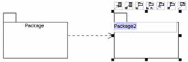
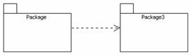
Method 1 �V Creating a dependency relationship using the Class
Diagram Palette
The dependency relationship link can be created between:
l A class ![]() and a class
and a class ![]() ,
,
l A packages ![]() and a package
and a package ![]() ,
or
,
or
l A class ![]() and a package
and a package ![]()
1. Click on the Dependency
button ![]() on the Class Diagram Palette. Drag from
the source diagram element to the target diagram element.
on the Class Diagram Palette. Drag from
the source diagram element to the target diagram element.
|
|
è |
|
2. Release the mouse button. A new dependency relationship link is created between the diagram elements.
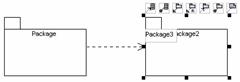
Method 2 �V Creating a dependency relationship link using the
resource centric interface
Diagram elements that a dependency relationship link can be created from, using the resource centric interface are:
l A class ![]() ,
and
,
and
l A package.
1. Click on an existing diagram element listed above on the diagram.
Resource icons appear around the diagram element.
2. Press on the resource icon with dependency (![]() ,
,![]() ,�K).
A new diagram element appears.
,�K).
A new diagram element appears.
3. Drag the new diagram element to the target diagram element. The new diagram element disappears. The target diagram element is selected.
|
|
è |
|
4. Release the mouse button. The dependency relationship link is
created between the diagram elements.

Method 1 �V Creating an association class using the Class Diagram
Palette
1. Click on the Association
class button ![]() on the Class Diagram Palette. Drag on the
association relationship link to the target class.
on the Class Diagram Palette. Drag on the
association relationship link to the target class.
2. Release the mouse button. The target class becomes an association
class.
Method 2 �V Creating an association class using the resource centric
interface

1. Click on an existing association relationship link. Resource icons
appear the association relationship link.
2. Press on the Association
class resource icon![]() .
A new class appears.
.
A new class appears.

3. Drag the class to the desired location. Release the mouse button.
4. Rename the newly created association class. Press Ctrl
+ Enter to finish the operation.
Creating
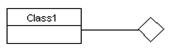
an N-ary Association between Classes
Method 1 �V Creating an n-ary association
between classes using the Class Diagram Palette
1. Click on the n-ary button ![]() on the Class Diagram Palette. Click on
the desired location on the diagram. A new n-ary
association element is created.
on the Class Diagram Palette. Click on
the desired location on the diagram. A new n-ary
association element is created.
2. Click on the newly created n-ary association element. Resource icons appear around the n-ary association element.
3. Click on one type of association
(Association ![]() ,
Aggregation
,
Aggregation ![]() ,
or Composition -> Class
,
or Composition -> Class ![]() )
on the Class Diagram Palette. Drag from the n-ary
association element to a class on the diagram.
)
on the Class Diagram Palette. Drag from the n-ary
association element to a class on the diagram.
4. Release the mouse button. A new association link is created between the class and the n-ary association element. Repeat the steps above to make the n-ary association element to link to more classes.
Method 2 �V Creating an n-ary association using
the resource centric interface
1. Click on the n-ary button ![]() on the Class Diagram Palette. Click on
the desired location on the diagram. A new n-ary
association element appears.
on the Class Diagram Palette. Click on
the desired location on the diagram. A new n-ary
association element appears.
![]()
2. Click on the newly created n-ary
association element. Resource icons appear around the n-ary
association element.

3. Click on one type of associations (![]() ,
, ![]() ,
,
![]() ,
�K). A new class appears.
,
�K). A new class appears.

4. Drag the new class to the desired location. Release the mouse button. The association is created between the new class and the n-ary association element.
|
|
è |
|
5. Repeat the steps above to make the n-ary association element to link to more classes.
Method 1 �V Creating an containment
relationship using the Class Diagram Palette
A containment relationship can be created
l Between a class ![]() and a class
and a class ![]() ,
,
l Between a package ![]() and any type of diagram elements,
and any type of diagram elements,
l Between a subsystem ![]() and any type of diagram elements,
and any type of diagram elements,
l Between a model ![]() and any type of diagram elements,
and any type of diagram elements,
1. Click on the Containment
button ![]() on the Class Diagram Palette. Drag from
the source diagram element to the target diagram element.
on the Class Diagram Palette. Drag from
the source diagram element to the target diagram element.
|
|
è |
|

2. Release the mouse button. A new containment relationship is created between the diagram elements.
Method 2 �V Creating containment relationship using the resource
centric interface
Diagram elements that a containment relationship can be created from, using the resource centric interface are:
l A class ![]() ,
,
l A package ![]() ,
,
l A subsystem ![]() ,
or
,
or
l A model ![]() ,
,
1. Click on an existing diagram element listed above on the diagram.
Resource icons appear around the diagram element.
2. Press on the Containment
-> Class button. A new class appears.

3. Drag the new class to the target diagram element. The target diagram element is selected.
|
|
è |
|
4. Release the mouse button. The containment relationship is created
between the diagram elements.
Method 1 �V Creating a blank new class diagram using with real time code generation the main menu
1. Click on File on the main
menu. The file menu appears.
2. Click on New Diagram on
the file menu. A cascading menu appears.
3. Click on New Class Diagram
with Real Time Code Generation on the cascading menu. A blank new class diagram
appears.
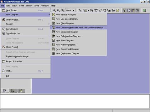
Method 2 �V Creating a blank new class diagram with real time code generation using the toolbar
1. Click on Create Class Diagram
![]() on the toolbar. A pop-up menu appears.
on the toolbar. A pop-up menu appears.
2. Click on Create Class Diagram with
Real Time Code Generation on the pop-up menu. A blank new class diagram
appears.
Method 3 �V Creating a blank
new class diagram using the Project Explorer
1. Right click on the Class
Diagram directory in the Project Explorer. A pop-up menu appears.
2. Click on Create Class Diagram
with Real Time Code Generation on the pop-up menu. A blank new class
diagram appears.
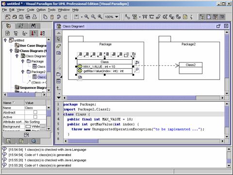
![]() Figure 9.4 A blank new class diagram is created.
Figure 9.4 A blank new class diagram is created.
Method 4 �V Real Time Code
Generation for an Existing Class Diagram
1. Right click on a blank place on an existing class diagram. A popup menu appears.
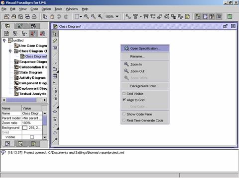
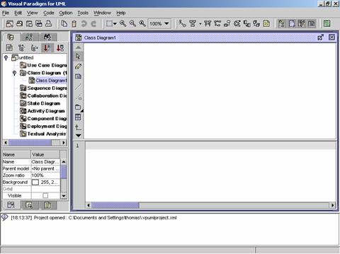
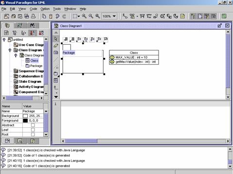
2. Check the Show Code Pane check box.
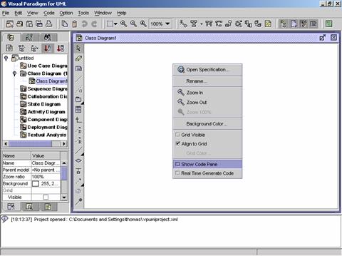
3. The Code Pane is shown below the class diagram.
4. Right click on the class diagram again. A popup menu appears.

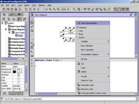
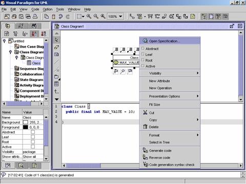
5. Check the Real Time Generate Code check box.
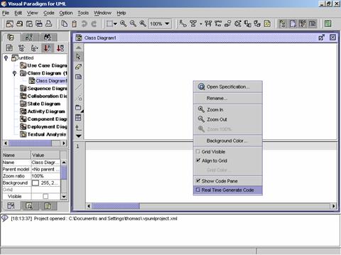
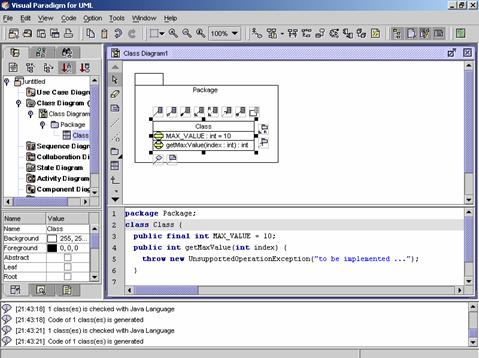
6. Click on any existing class in the class diagram. The code will be generated in the Code Pane.
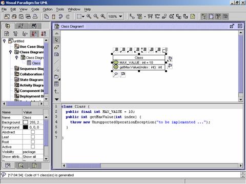
1. Create a new class on the class diagram. The generated code for the class is shown in the Code Pane.
2. Right click on the class. A popup menu appears.
3. Check the Abstract check box. The code is update immediately.
4. Right click on the class. A popup menu appears.
5. Click on Open Specification on the popup menu. The Class
Specification dialog appears.

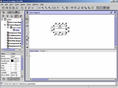
6. Click on the Java Class Code
Detail tab in the Class
Specification dialog. The class can be set to final or interface.
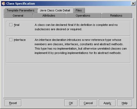
7. Check the interface check box. The code will be updated.
1. Right click on an existing class on the class dialog. A popup menu
appears.
2. Click on New Attribute on the popup menu. A new attribute is added to the class and the code in the Code Pane is updated at the same time.
3. Right click on the class. A popup menu appears.
4. Click on Open Specification
on the popup menu. The Class
Specification dialog appears.
5. Click on the Attributes
tab in the Class Speciation dialog.
A list of attributes is shown.
6. Double click on an attribute. The Attribute Specification dialog appears.
7. Edit the attribute properties �V Name, Initial Value, Visibility and Type.
8. Click on the Java Attribute Code Detail tab on the Attribute Specification dialog. Check the final check box.
9. Click on the OK button on the Attribute Specification dialog to close it. The Class Specification dialog is active again.
10. Click on the OK button on the Class Specification dialog to close it. The code for the attribute is updated.

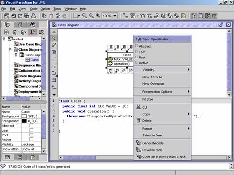
1. Right click on an existing class. A popup menu appears.
2. Click on New Operation on
the popup menu. A new operation is added to the class and the code generated
for the operation is added to the Code
Pane.

3. Right click on the class. A popup menu appears.
4. Click on Open Specification on the popup menu. The Class Specification dialog appears.
5. Click on the Operations tab in the Class Specification dialog. A list of operations is shown.
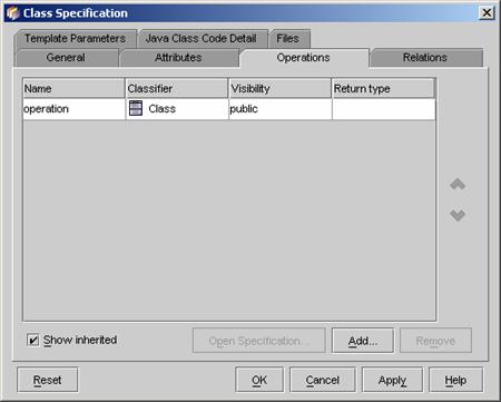
6. Double click on an operation. The Operation Specification dialog appears.
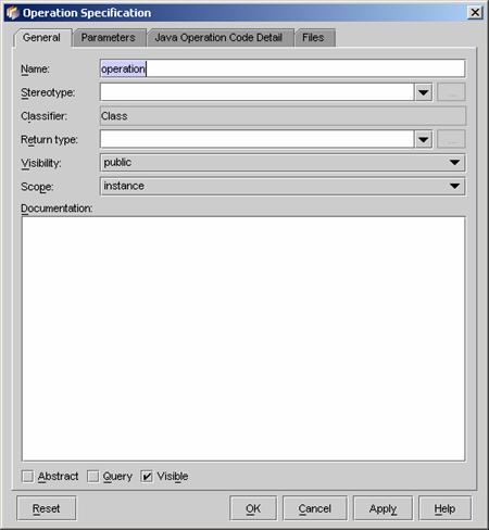
7. Edit the operation properties �V Name and Return Type.
8. Click on the Java Operation Code Detail tab in the Operation Specification dialog.
9. An operation can be set to be final, native or synchronized. Click on the Parameters tab in the dialog
10. Click on the Add�K button to add a parameter. The Parameter Speciation dialog appears.

11. Edit the parameter properties �V Name and Type.
12. Click the Java Parameter Code Detail in the Parameter Specification dialog.
13.
A parameter can be set to be final. Click on the OK button in the dialog to close it.
The Operation Specification dialog
is active again.
14. A new parameter is added to the operation. Click the OK button to close the Operation Speciation dialog. The Class Specification dialog is active again.
15. Click the OK button in the Class Specification dialog. The code generated for the operation is updated.
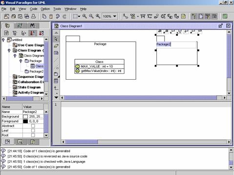
1. Create a new package on the class diagram.
2. Place an existing class in the package. The code generated for the class is updated.
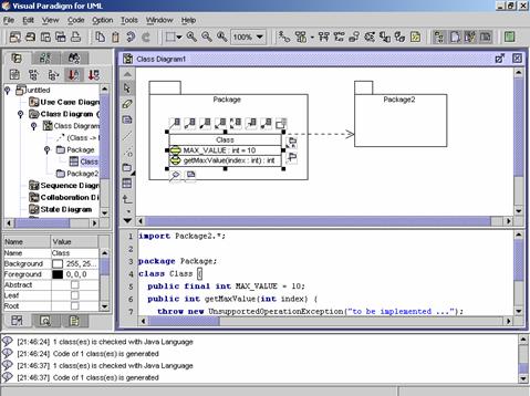
1. Create a new package on the class diagram.
2. Create a dependency relationship between an existing class and the new package. The code generated for the class is updated.
1. Create a new class on the class diagram.
2. Create a dependency relationship between a class and the new class. The code generated for the importing class is updated.
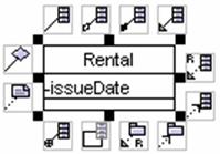
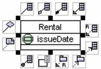
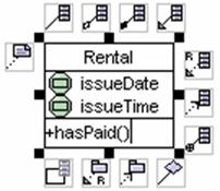
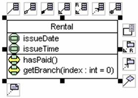
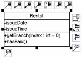
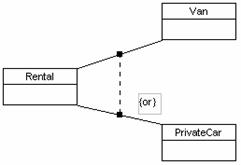
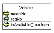
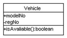
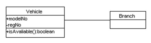
1. Click on the class button on the Class Diagram Palette. Click on the desired location on the class diagram. A new class appears. Rename the class as ��Vehicle��. Then right click on the class. A pop-up menu appears. Click on New Attribute on the pop-up menu. A new attribute is added to the class. Double click on the new attribute. A text box appears. Type ��-regNo�� in the text box. (- for private, + for public, # for protected). Add more attributes: -modelNo, . Add more operations: +isAvailable():Boolean, .
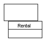
2. Right click on the Vehicle class. A pop-up menu appears. Click on Visibility Option on the pop-up menu. A cascading menu appears. Click on UML Style on the cascading menu.
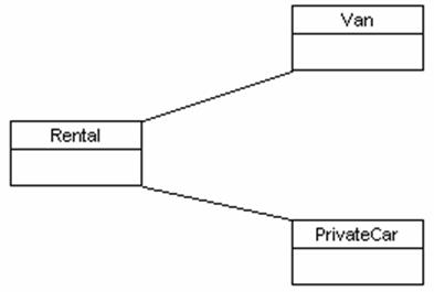
3. Click on the Vehicle class. Resource icons appear around the class. Click on the Association -> Class resource icon. A new class appears. Drag the new class to the desired location. Rename the new class as ��Branch��. An association relationship is created between the classes.
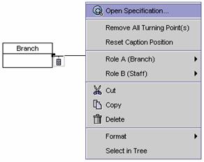
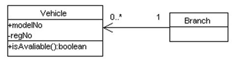
4. Right click on the association link. A pop-up menu appears. Click on Role A(Vehicle). A cascading menu appears. Click on Multiplicity on the cascading menu. A list of multiplicities appears. Click on 0..*. The multiplicity of Vehicle role is set to 0..*. Right click on the association link again. A pop-up menu appears. Click on Role B(Branch) in the pop-up menu. A cascading menu appears. Click on Multiplicity on the cascading menu. A list of multiplicities appears. Click on 1 on the cascading menu. The multiplicity of the Branch role is set to 1. Right click on the new association link. A pop-up menu appears. Click on Role B(Branch). A cascading menu appears. Uncheck the Navigable checkbox on the cascading menu.
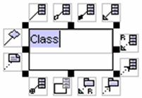
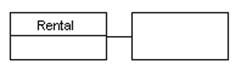
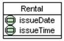
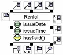
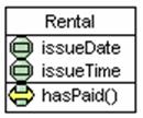
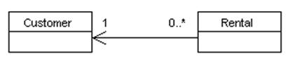
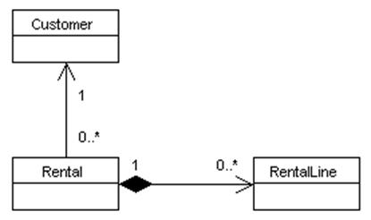
5. Create a new class. Rename the class as ��Rental��. Then create another new class and rename the class as ��Customer��. Create an association relationship link between the Customer class and Rental class. Set the multiplicity of Customer role to 1 and the Rental role to 0..*. Right click on the new association link. A pop-up menu appears. Click on Role B(Rental) on the pop-up menu. A cascading menu appears. Uncheck the Navigable checkbox on the cascading menu.
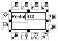
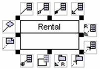
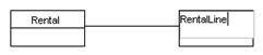
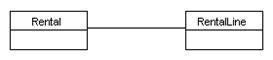
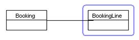
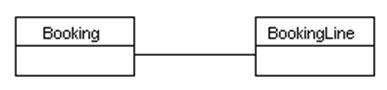
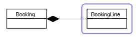
6. Click on the Rental class. Resource icons appear around the class. Click on Composition -> Class resource icon. A new class appears. Drag the new class to the desired location. Rename the new class as ��RentalLine��. A composition relationship is created between the classes. Set the multiplicity of Rental role to 1 and RentalLine role to 0..*., and set the Rental role to not navigable.
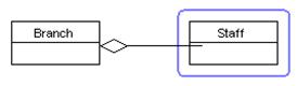
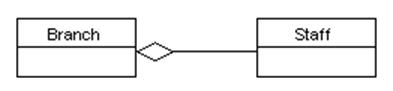
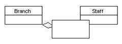
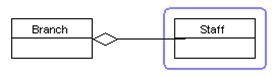
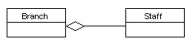
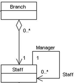
7. Click on the Branch class. Resource icons appear around the class. Click on Aggregation -> Class resource icon. A new class appears. Drag the new class to the desired location. Rename the new class as ��Staff��. A composition relationship link is created between the classes. Set the multiplicity of Staff role to 1 and of Branch role to 0..*.
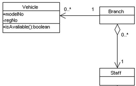
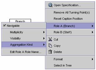
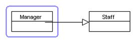
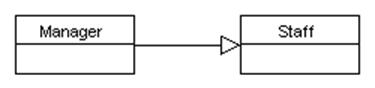
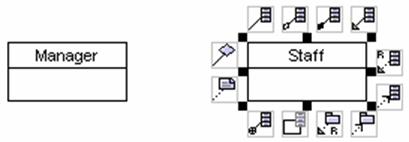
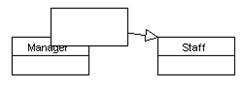
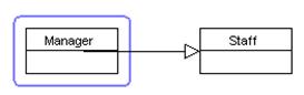
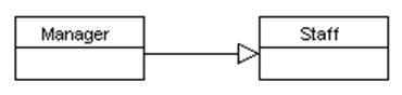
8. Click on the Staff class. Resource icons appear around the class. Click on Self Association resource icon. A new self association link is created with the class. Right click on the self association. A pop-up menu appears. Click on Role A(Staff) in the pop-up menu. A cascading menu appears. Click Edit Role A Role name on the cascading menu. A text box appears. Type in ��Manager�� as the role name. Right click on the self association again. A pop-up menu appears. Click on Role B(Staff) in the pop-up menu. A cascading menu appears. Click Edit Role B Rolename on the cascading menu. A text box appears. Type in ��Staff�� as the role name. Set the Role A multiplicity to 1 and Role B multiplicity to 0..*. Set the Role A to not navigable.
9. Below is the completed class diagram.
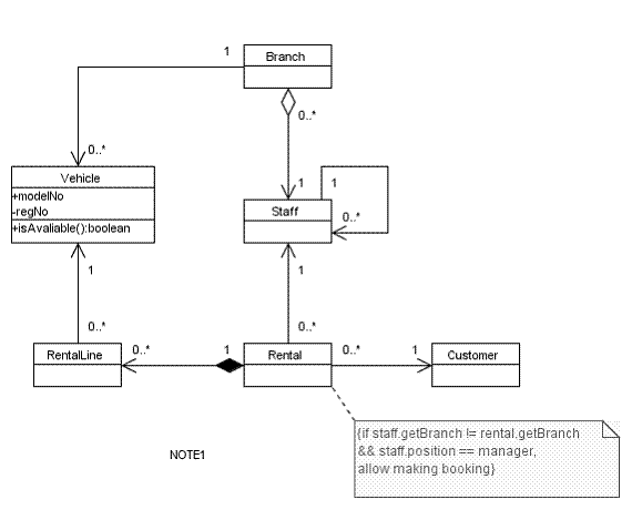
Draw the diagram below according to the guidelines given in this chapter.
![]() Figure 9.5 A class diagram
Figure 9.5 A class diagram