Component Diagram
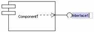
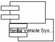
A component diagram is a simple, high-level diagram that shows the organization of and dependencies among a set of components. Component diagrams address the static implementation view of a system. There is usually a one-to-one relationship between package diagrams and component diagrams.
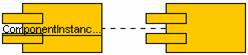
![]() Figure 10.1 Component Diagram
Figure 10.1 Component Diagram
We
use component diagram when we model the static implementation view of a system
such as modeling source code, executable releases, physical databases, and
adaptable systems.
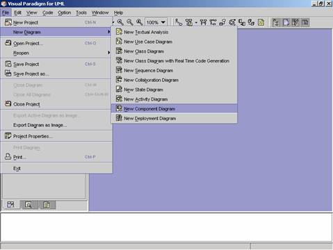
Method 1 �V Creating a Component Diagram using the
Menu Bar
1. Click on File on the menu bar. The file menu appears.
2. Click on New Component on the file menu. A cascading menu appears.
3. Click on New Component Diagram on the cascading menu. A blank new component diagram appears.
Method 2 �V Creating a Component Diagram using the
Toolbar
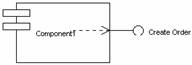
1.
Click on Create
New Component Diagram
![]() icon on the toolbar. A blank new
component diagram appears.
icon on the toolbar. A blank new
component diagram appears.
Method 3 �V Creating a Component
Diagram using the Project Explorer
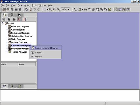
1. Right click on Component Diagram directory in the Project Explorer. A pop-up menu appears.
2. Click on Create Component Diagram. A blank new component diagram appears.
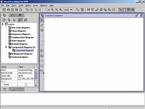
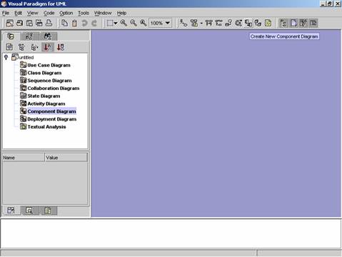
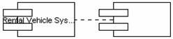
![]() Figure 10.2 A blank new component diagram is
created
Figure 10.2 A blank new component diagram is
created
|
|
Icon |
Notation |
Definition |
|
|
Note |
A note is used for comments additional
explanation, specification and requirement in a diagram element or at a link
in the diagram. It is not included in generated code. The contents of a note do not alter
the meaning of the model to which it is attached. A note can contain any combination
of text and graphics. It can also be used in defining a stereotype and
entering a noted element. (adapted from UMLUG-purple) |
|
|
|
Anchor |
An anchor is to line a diagram element and
a note. |
|
|
|
Dependency |
The dependency is a semantic relationship
between the two elements. It indicates that when a change occurs in one
element, there may be a change necessary to the other element. A dependency link can include label
and stereotype can be set |
|
|
|
Constraint |
|
|
|
|
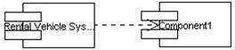
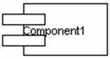
Component |
A component is a physical and replaceable
part of a system that conforms to and provides the realization of a set of
interfaces. Components represent all kinds of elements pertaining to the
piecing together of software applications. They could be simple files or
dynamically loaded libraries. |
|
|
|
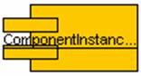
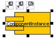
Component Instance |
Instance of a component. |
|
|
|
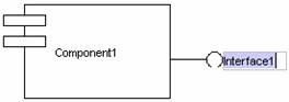
Interface |
An interface is a collection of operations
that are used to specify a service of a class or a component. Each interface
often specifies only a limited part of the behavior of an actual class. Characteristics of interface are: (i) do not have internal structure
specification; (ii) do not have implementation; (iii) lack of attributes, states and
associations; (iv) have operations only; (v) may have generalization relationships. |
|
|
|
Object |
Object can be viewed as an
entity at a particular point in time with a specific value and as a holder of
identity that has different values over time. Associations among objects are not
shown. When you place an object tag in the design area, a lifeline is
automatically drawn and attached to that object tag. |
|
|
|
Subsystem |
A subsystem groups use cases or packages
together. |
|
|
|
Package |
A package is a mechanism for organizing
elements into groups. It is used
in the Use Case, Class, and Component diagrams. Packages may be nested within other
packages. A package may contain both subordinate packages and ordinary model
elements. The entire system
description can be thought of as a single high-level subsystem package with
everything else in it. |
![]() Table 2 The Component Diagram Palette of VPUML
Table 2 The Component Diagram Palette of VPUML
Method 1 �V Creating a component
using the diagram palette
1.
To create a component in your
component diagram, click on the Component
button ![]() on the diagram palette and click on the
desire location. A component appears.
on the diagram palette and click on the
desire location. A component appears.
![]()
2. Rename the component name, and then press Ctrl + Enter to set the component name.
|
|
è |
|
3. The component name is set.
![]()
Method 2 �V Creating a component
using the resource centric interface
Diagram element that a component can be created from, using the resource centric interface is:
l Component ![]()
1. Click on the component. The resource icons appear around the diagram element.
|
|
è |
|
2. Press mouse button on the Component
resource icon![]() .
A new component appears.
.
A new component appears.
3. Drag the component to the desired location. The component is created.
|
|
è |
|
Method
1 �V Creating a Component Instance using the diagram palette
To create a Component Instance in your
component diagram, click on the Component
Instance button ![]() on the diagram palette and click on the
diagram window. A component instance appears.
on the diagram palette and click on the
diagram window. A component instance appears.
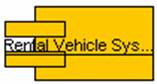
1. Rename the newly created Component Instance name, and then press Ctrl + Enter to finish the operation.
|
|
è |
|
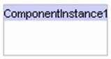
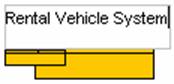
2. The Component Instance name is set.
Method
2 �V Creating a Component Instance using the resource centric interface
Diagram element that a component instance can be created from, using the resource centric interface is:
l
Component Instance ![]()
1. Click on an existing component instance. The resource icons appear around the diagram element.
|
|
è |
|
2.
Press on the Component
Instance resource icon![]() .
A new component instance appears.
.
A new component instance appears.

3. Drag the component instance to the desired location. Release the mouse button. The component instance is created.
|
|
è |
|

Creating an Interface
Method
1 �V Creating an Interface using the diagram palette
1.
To create an Interface in your
component diagram, click on the Interface
icon ![]() on the diagram palette and then click on the
desired location on the diagram. A new interface is created.
on the diagram palette and then click on the
desired location on the diagram. A new interface is created.
2. Rename the newly created interface name. Press Ctrl + Enter to finish the operation.
3. The Interface name is set.
Method
2 �V Creating an Interface using the resource centric interface
Diagram elements that an interface can be created from, using the resource centric interface are:
l
Component ![]()
l
Component Instance ![]()
|
|
è |
|
1.
Press on the Interface
resource icon![]() .
A new interface appears.
.
A new interface appears.

2. Drag the interface to the Component or Component Instance that you want the interface to be placed in. Release the mouse button. The Interface is created.
|
|
è |
|