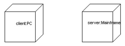
Deployment Diagram
l
Shows the configuration of run
time processing nodes and the components that live on them
l Shows a set of nodes and their relationships
l
Illustrates the static
deployment view of an architecture
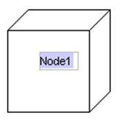
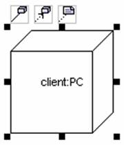
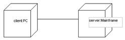
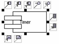
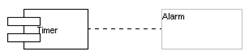
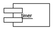
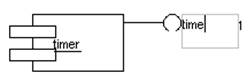
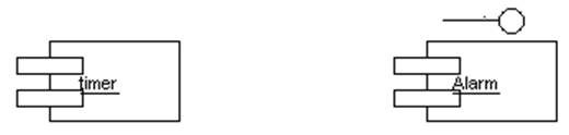
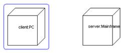
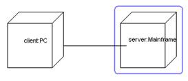
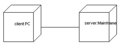
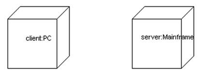
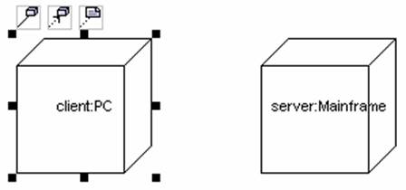
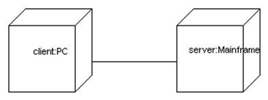
![]() Figure 11.1 Deployment Diagram
Figure 11.1 Deployment Diagram
We use Deployment Diagram when we model the
static deployment view of a system such as embedded systems, client/server
systems, and fully distributed systems.
In addition, developers place component diagrams on top of deployment
diagrams to indicate which modules of code will go on which hardware platform.
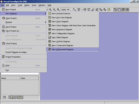
Method 1 �V Creating the Deployment Diagram using the Menu Bar
1. Click on File in the menu
bar. The file menu appears.
2. Click on New Diagram in
the file menu. A cascading menu appears.
3. Click on New Deployment
Diagram on the cascading menu. A new Deployment Diagram appears.
Method 2 �V Creating the Deployment Diagram using the Toolbar
1. Click on the Create Deployment
Diagram ![]() icon in the toolbar. A new Deployment
Diagram appears.
icon in the toolbar. A new Deployment
Diagram appears.
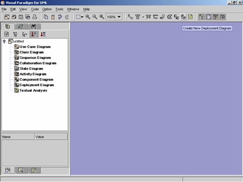
Method 3 �V Creating the Deployment Diagram using the Project
Explorer
1. Right click on Deployment
Diagram directory in the Project Explorer. A pop-up menu appears.
2. Click on Create Deployment
Diagram. A new Deployment Diagram appears.
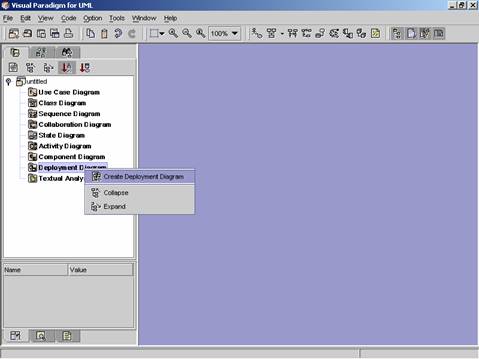
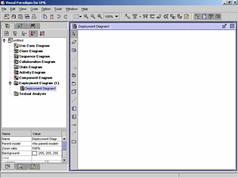
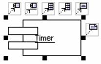
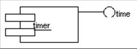
Figure 11.5 A new deployment diagram is created.
|
|
Icon |
Notation |
Definition |
|
|
Note |
A note is used for comments additional explanation,
specification and requirement in a diagram element or at a link in the
diagram. It is not included in generated code. The contents of a note do not alter
the meaning of the model to which it is attached. A note can contain any
combination of text and graphics. It can also be used in defining a
stereotype and entering a noted element. (adapted from UMLUG-purple) |
|
|
|
Constraint |
|
|
|
|
Anchor |
An anchor is used to line a diagram element and a
note. |
|
|
|
Subsystem |
A subsystem groups diagram elements together. |
|
|
|
Package |
A package is a mechanism for organizing elements
into groups. It is used in the
Use Case, Class, and Component diagrams.
Packages may be nested within other packages. A package may contain
both subordinate packages and ordinary model elements. The entire system description can be
thought of as a single high-level subsystem package with everything else in
it. |
|
|
|
Node |
A node is a physical element that exists at run time
and represents a computational resource, generally having at least some
memory and often processing capability. It is a run-time physical object and
can be a Type or Instance. It can contain components and objects. |
|
|
|
Node Instance |
|
|
|
|
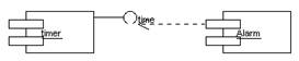
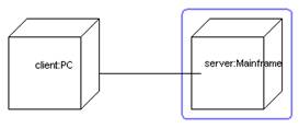
Association |
The link is used to associate one node to the other
node. |
|
|
|
Component |
A component is a physical and replaceable part of a
system that conforms to and provides the realization of a set of
interfaces. Components represent
all kinds of elements pertaining to the piecing together of software
applications. They could be simple files or dynamically loaded libraries. |
|
|
|
Component Instance |
Instance of Component |
|
|
|
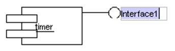
Interface |
An interface is a collection of operations that are used to specify a
service of a class or a component. Each interface often specifies only a
limited part of the behavior of an actual class. Characteristics of interface
are: (i) do not have internal structure specification; (ii) do not have
implementation; (iii) lack of attributes, states and associations; (iv) have
operations only; (v) may have generalization relationships. |
|
|
|
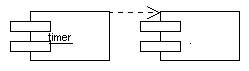
Dependency |
Dependency is a semantic relationship between the
two elements. It indicates that when a change occurs in one element, there
may be a change necessary to the other element. A dependency link can include label
and stereotype can be set. |
|
|
|
Object |
Object can be viewed as an entity at a particular
point in time with a specific value and as a holder of identity that has
different values over time.
Associations among objects are not shown. When you place an object tag
in the design area, a lifeline is automatically drawn and attached to that
object tag |
|
|
|
|
|
![]() Table 11.1 Deployment Diagram Palette
Table 11.1 Deployment Diagram Palette
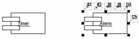
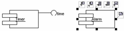
Create Node
Method
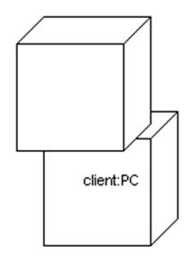
1 �V Creating a node using the deployment diagram palette
1.
Click on the node button ![]() in the deployment diagram palette. Click on
the desired location in the diagram. A new note appears.
in the deployment diagram palette. Click on
the desired location in the diagram. A new note appears.
2. Rename the newly added note. Press Ctrl + Enter to finish the operation.
|
|
è |
|
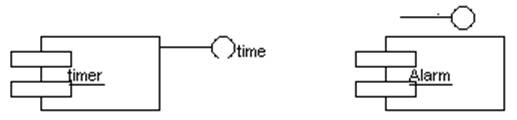
Method
2 �V Creating a node using the resource centric interface
1.
Click on an existing node in
the diagram. Resource icons appear around the node.
2.
Press on the resource icon with
node (![]() ,
�K). A new node appears.
,
�K). A new node appears.
3. Drag the node to the desired location. Release the mouse button.
|
|
è |
|
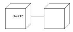
4. Rename the newly added node. Press Ctrl + Enter to finish the operation.
|
|
è |
|

Method
1 �V Creating a component using the deployment diagram palette
1.
Click on the component button ![]() in the deployment diagram palette. Click
on the desired location in the diagram. A new component appears.
in the deployment diagram palette. Click
on the desired location in the diagram. A new component appears.
2. Rename the newly added component. Press Ctrl + Enter to finish the operation.
|
|
è |
|
Method
2 �V Creating a component using the resource centric interface
List of diagram elements that can create component with dependency using resource centric approach:
l
Component ![]()
l
Interface ![]()
1.
Click on an existing diagram
element listed above in the diagram. Resource icons appear around the diagram
element.
2.
Press on the resource icon with
component (![]() ,
�K). A new component appears.
,
�K). A new component appears.
3. Drag the component to the desired location. Release the mouse button.
|
|
è |
|
4. Rename the newly added component. Press Ctrl + Enter to finish the operation.
|
|
è |
|
Method
1 �V Creating a component Instance using the deployment diagram palette
1.
Click on the component instance button ![]() in the deployment diagram palette. Click
on the place required in the diagram. A new component instance appears.
in the deployment diagram palette. Click
on the place required in the diagram. A new component instance appears.
2. Rename the newly added component instance. Press Ctrl + Enter to finish the operation.
|
|
è |
|
Method
2 �V Creating a component instance using the resource centric interface
List of diagram elements that can create component instance with dependency using resource centric approach:
l
Component Instance ![]()
l
Interface ![]()
1.
Click on an existing diagram
element listed above in the diagram. Resource icons appear around the diagram
element.
2.
Press on a resource icon with component
instance (![]() ,
�K). A new component instance appears.
,
�K). A new component instance appears.
3. Drag the component instance to the desired location. Release the mouse button.
|
|
è |
|
4. Rename the newly added component instance. Press Ctrl + Enter to finish the operation.
|
|
è |
|
Method
1 �V Creating an interface using the deployment diagram palette
1.
Click on the interface button ![]() in the deployment diagram palette. Click
on the desired location in the diagram. A new interface appears.
in the deployment diagram palette. Click
on the desired location in the diagram. A new interface appears.
2. Rename the newly added interface. Press Ctrl + Enter to finish the operation.
|
|
è |
|
Method
2 �V Creating an interface using the resource centric interface
List of diagram elements that can create interface with dependency using resource centric approach:
l
Component ![]()
l
Component Instance ![]()
1.
Click on an existing diagram
element listed above in the diagram. Resource icons appear around the diagram
element.
2.
Press on the resource icon with
interface (![]() ,
�K). A new interface appears.
,
�K). A new interface appears.
3. Drag the interface to the desired location. Release the mouse button.
|
|
è |
|
4. Rename the newly added interface. Press Ctrl + Enter to finish the operation.
|
|
è |
|
1.
Click on the object button ![]() in the activity diagram palette. Click on
the desired location in the diagram. A new object appears.
in the activity diagram palette. Click on
the desired location in the diagram. A new object appears.
2. Rename the newly added object. Press Ctrl + Enter to finish the operation.
|
|
è |
|
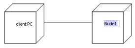
Method
1 �V Creating an association using the use case diagram palette
An association relationship can be created between nodes.
1.
Click on the association button ![]() in the use case diagram palette. Drag
from the source actor or the target node.
in the use case diagram palette. Drag
from the source actor or the target node.
|
|
è |
|
2. Release the mouse button. A new association is created between the nodes.
Method
2 �V Creating an association using the resource centric interface
An association can be created between notes using resource centric interface.
1.
Click on an existing node in
the diagram. Resource icons appear around the node.
2.
Press on the association -> node
![]() .
A new node appears.
.
A new node appears.
3. Drag the new node to the target node. The target is selected.
|
|
è |
|
4.
Release the mouse button. The
association is created between the nodes.
Method
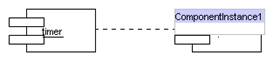
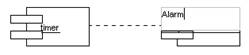
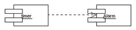
1 �V Creating a dependency relationship using the class diagram palette
A dependency relationship can be created between:
l
A component ![]()
l
A component Instance ![]()
l
An interface ![]() (Cannot be the source diagram element)
(Cannot be the source diagram element)

1.
Click on the dependency button ![]() in the class diagram palette. Drag from
the source diagram element to the target diagram element.
in the class diagram palette. Drag from
the source diagram element to the target diagram element.
|
|
è |
|
2. Release the mouse button. A new dependency relationship is created between the diagram elements.
Method
2 �V Creating a dependency relationship using the resource centric interface
List of diagram elements that can create dependency relationship between them using resource centric interface :
l
A component ![]()
l
A component Instance ![]()
l
An interface ![]()
1.
Click on an existing diagram
element listed above in the diagram. Resource icons appear around the diagram
element.
2.
Press on a resource icon with dependency
(![]() ,
,![]() ,
�K). A new diagram element appears. (Note: the resource icon must be
correspondent to the target diagram element)
,
�K). A new diagram element appears. (Note: the resource icon must be
correspondent to the target diagram element)
3. Drag the new diagram element to the target diagram element. The target diagram element is selected.
|
|
è |
|
Release the mouse button. The dependency
relationship is created between the diagram elements.