Sequence Diagram
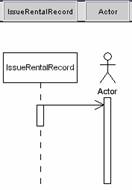
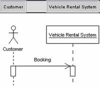
A Sequence diagram is a model that describes how groups of objects collaborate in some behavior over time and capturing the behavior of a single use case. It shows the objects and the messages that are passed between these objects in the use case.
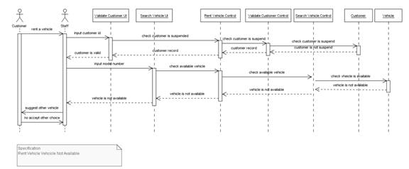
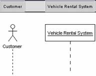
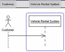
![]() Figure 2.1 Sequence Diagram
Figure 2.1 Sequence Diagram
l A good design can have lots of small methods in different classes. Because of this, it can be difficult to figure out the overall sequence of behavior. This diagram is simple and visually logical, so it is easy to see the sequence of the flow of control. It also clearly shows concurrent processes and activations in a design.
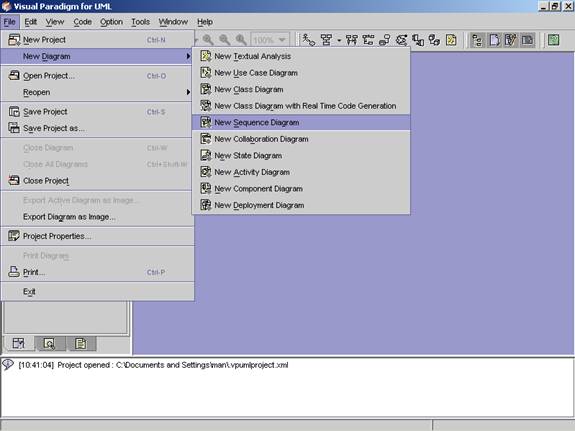
Method 1 �V Creating a Sequence Diagram using the
Menu Bar
1. Click on File on the menu bar. The file menu appears.
2. Click on New Diagram on the file menu. A cascading menu appears.
3. Click on New Sequence Diagram on the cascading menu. A blank new sequence diagram appears.
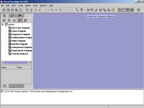
Method 2 �V Creating Sequence Diagram using the
Toolbar
1.
Click the Create
Sequence Diagram button![]() on the toolbar. A blank new sequence diagram appears.
on the toolbar. A blank new sequence diagram appears.
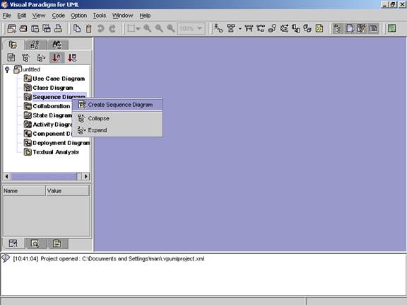
Method 3 �V Creating a Sequence Diagram using
the Project Explorer
1. Right click on the Sequence Diagram directory in the Project Explorer. A popup menu appears.
2. Click on Create Sequence Diagram. A blank new sequence diagram appears.
![]() Figure 2.5 A blank new sequence diagram is
created.
Figure 2.5 A blank new sequence diagram is
created.
|
|
Icon |
Notation |
Definition |
|
|
Note |
A note can be used for comments additional
explanation, specification and requirement in a diagram element or at a link
in the diagram. The contents of a
note do not alter the meaning of the model to which it is attached. It can
contain any combination of text and graphics. It can also be used in defining
a stereotype and entering a noted element. (adapted from UMLUG-purple) |
|
|
|
Anchor |
An anchor is to link a diagram element and a note. |
|
|
|
Constraint |
A constraint is a semantic condition or restriction on model elements
that must be enforced by a correct design of a system. It is represented as a linguistic, enclosed in
braces ({}), statement in some formal (OCL, C++, and other), or natural language. There are 14 standard
constraints in the UML such as association,
global, parameter. You may also define your own constraints. |
|
|
|
Subsystem |
A subsystem groups use cases or packages together. |
|
|
|
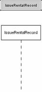
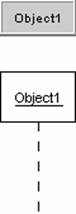
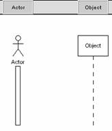
Object |
Object can be viewed as an entity at a particular
point in time with a specific value and as a holder of identity that has
different values over time.
Associations among objects are not shown. When you place an object tag
in the design area, a lifeline is automatically drawn and attached to that
object tag. |
|
|
|
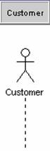
Actor |
An actor represents a coherent set of roles that
users of a system play when interacting with the use cases of the
system. An actor participates in
use cases to accomplish an overall purpose. An actor can represent the role of a
human, a device, or any other systems. |
|
|
|
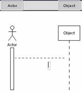
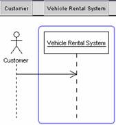
Message |
A message is a sending of a signal from one sender
object to other receiver object(s). It can also be the call of an operation
on receiver object by caller object. The arrow can be labeled with the name
of the message (operation or signal) and its argument values. A sequence number that shows the
sequence of the message in the overall interaction as well as a guard
condition can also be labeled at the arrow. |
|
|
|
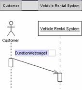
Duration Message |
A message that indicates an action will cause
transition from one state to another state. |
|
|
|
Self Message |
A message that indicates an action will perform at a
particular state and stay there. |
|
|
|
Create Message |
A message that indicates an action that will perform
between two states. |
|
|
|
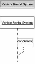
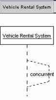
Concurrent |
Concurrent means several actions of the same type
can be executed simultaneously. |
|
|
|
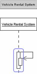
Recursive |
Action state that enables repeated actions. |
![]() Table 2.1 The Sequence Diagram Palette of VPUML
Table 2.1 The Sequence Diagram Palette of VPUML
Method 1
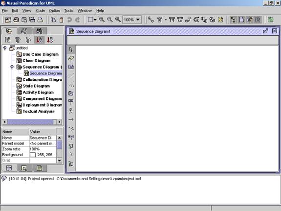
�V Creating an Actor using the Diagram Palette
1. To create an actor in your sequence diagram, click on the Actor button ![]() on the diagram palette and click on the
desired location on diagram. A new actor is created.
on the diagram palette and click on the
desired location on diagram. A new actor is created.
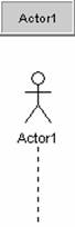
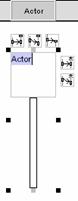
2. Rename the newly created actor name. Press Ctrl + Enter to finish the operation.
|
|
è |
|
3. The actor name is set.
![]()
Double-click on the toolbar button to set the button as default on
the toolbar.
(Press Escape or click
on any other button to de-select)
Method 2
�V Creating an actor using the resource centric interface
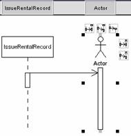
Diagram element that an actor can be created from, using the resource centric interface is:
l Object ![]()
1. Click on an existing object on the diagram. Resource icons appear around the object.
|
|
è |
|
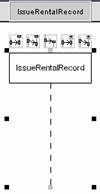
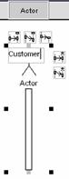
2. Press one of the resource icons with Object (![]() ,
,![]() ).
A new actor appears.
).
A new actor appears.
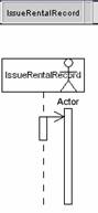
3. Drag the actor to the desired location. The actor is created.
|
|
è |
|
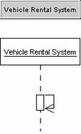
Method 1 �V Creating an Object using the
diagram palette
1.
Creating an object in your
sequence diagram, click on the Object
button ![]() on the diagram palette and click on the desired
location on the diagram. A new object appears.
on the diagram palette and click on the desired
location on the diagram. A new object appears.
2. Rename the newly created object. Press Ctrl + Enter to finish the operation.
|
|
è |
|
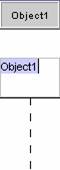
3. The object name is set.
Method 2 �V Creating an object using the resource
centric interface
Diagram element that an object can be created from, using the resource centric interface is:
l
Actor ![]()
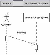
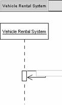
Creating a Message
Method 1 �V Creating a message using the diagram
palette
1.
Click on the Message button ![]() on the diagram palette.
on the diagram palette.
2.
Click anywhere on the message
sender, and drag to the target diagram element.
|
|
è |
|

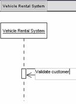
3. Rename the newly created message.
|
|
è |
|
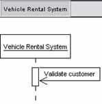
![]()
When message is being dragged, a new focus of control will create. There are two methods to maintain the message connected to the same focus of control and not to create a new one.
1. Drag the message with a little of distance each time.
2. Press the Shift button when dragging the message.
Method 1 �V Creating a Constraint using the diagram
palette
1.
Click on the Constraint button ![]() on the diagram palette.
on the diagram palette.
2.
Click anywhere on the source
diagram element. Drag to the target diagram element.
|
|
è |
|

3. Input the constraint in the text field. Press Ctrl + Enter to finish the operation.
|
|
è |
|

Method 1 �V Creating a Duration Message using the
diagram palette
1.
Click on the Duration Message
button ![]() on the diagram palette.
on the diagram palette.
2.
Click anywhere on the source
diagram element. Drag to the target diagram element.
|
|
è |
|
3. Rename the newly created duration message. Press Ctrl + Enter to finish the operation.
|
|
è |
|
Method 1 �V Creating a Self Message using the diagram
palette
1.
Click on the Self Message button ![]() on the diagram palette.
on the diagram palette.
2. Click on an existing object or the focus of control that you want to create self message.
3. Press F2 to rename the self message. Press Ctrl + Enter to finish the operation.
|
|
è |
|
4. The self message name is set.
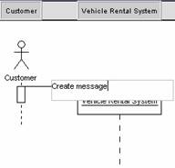
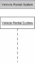
Method 1 �V Creating a Create Message using the
diagram palette
1.
Click on the Create Message
button ![]() on the diagram palette.
on the diagram palette.
2. Press on an existing diagram element. Drag to the target diagram element.
|
|
è |
|
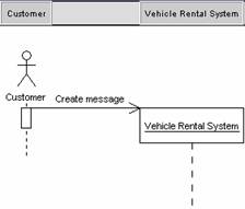
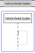
3. Press F2 to rename the newly created create message. Press Ctrl + Enter to finish the operation.
|
|
è |
|
4. The create message name is set.
Method 1 �V Creating a concurrent using the
diagram palette
1.
Click on Concurrent
button ![]() on the diagram palette.
on the diagram palette.
2. Click on an existing object that you want to create concurrent.
3. Rename the newly created concurrent. Press Ctrl + Enter to finish the operation.
4. The concurrent name is set.
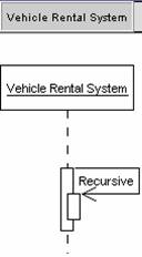
Method 1 �V Creating a recursive using the
diagram palette
1.
Click on Recursive
button ![]() on the diagram palette.
on the diagram palette.
2. Click on an existing object that you want to create recursive.
3. Rename the newly created recursive. Press Ctrl + Enter to finish the operation.
|
|
è |
|
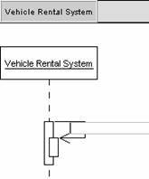
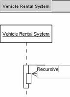
4. The recursive name is set.
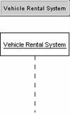
Method 1 �V Creating a Subsystem using the
diagram palette
1.
Creating a subsystem in your
sequence diagram, click on the Subsystem
button ![]() on the diagram palette and click on the
desired location on the diagram. A new subsystem appears.
on the diagram palette and click on the
desired location on the diagram. A new subsystem appears.
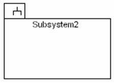
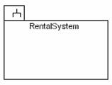
2. Rename the newly created subsystem. Press Ctrl + Enter to finish the operation.
|
|
è |
|
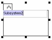
3. The subsystem name is set.
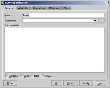
1. Right click on an existing actor that you want to edit. A popup menu appears.
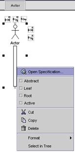
2. Click on Open Specification on the pop-up menu. The Specification dialog box appears. The name, description and so on can be modified in the dialog box.
1. Right click on an existing object. A popup menu appears.
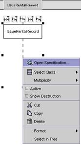
2. Click on Open Specification on the popup menu. A Specification dialog appears. The name, description and so on can be modified in the dialog.
1. Right click on an existing message that you want to edit.
2. A popup menu is appears, choose the message type you want.
|
|
è |
|
3. The popup menu disappears, and the message type is set.
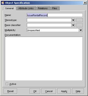
Method 1 �V Setting in the Object Specification dialog
1. Right click on an existing object. A popup menu appears.
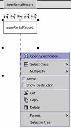
2. Click on Open
Specification on the popup menu. A Specification dialog appears. 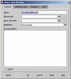
3. Click on Base
classifier, a list will be display
showing all the class in the current project.
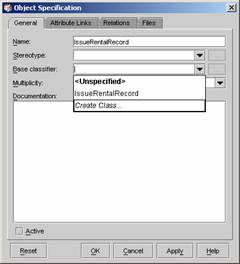
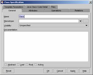
4. Click on an existing class or click
on Create Class to create a new class. Click
on Create Class, the Class
Specification dialog appears. Setting
the new class property, then click OK button.
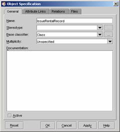
5. The Base classifier is set. Click OK to finish the operation.
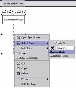
Method 2 �V Setting in the Popup menu
1. Right click on an existing object. A popup menu appears.
2. Click on Select Class on the popup menu. A submenu appears. Click on Create Class to create a new class or click on an existing class. To search a class, enter the class name in the Search textfield.
1. Right click on an existing object. A popup menu appears.
2. Click on Active on the popup menu.
3. The object is setted to active.
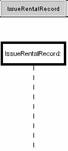
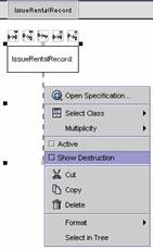
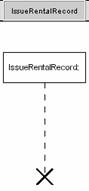
1. Right click on an existing object. A popup menu appears.
2. Click on Show Destruction on the popup menu.
3. The object is setting to show Destruction.
1. Open a collaboration diagram from the Project Explorer. Double click on a blank place on the diagram to generate a new sequence Diagram.
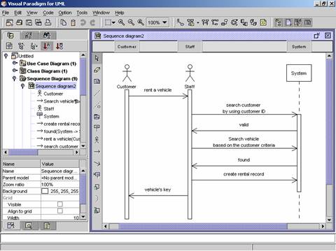
2. A new sequence diagram is generated.
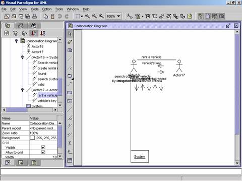
3. A new sequence diagram is generated from the collaboration diagram.
=>
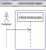
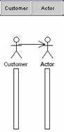
1. Click on the Actor button on the toolbar and click on the desired location on diagram. A new actor is created.
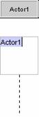
2. Rename the newly created actor as ��Customer��. Press Ctrl + Enter to finish the operation.
|
|
è |
|
è |
|
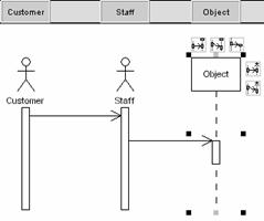
3. Select the newly created actor, the resource icons appear around it. Press Actor Resource icon, and then drag to right side and release the mouse button. A new actor is created.
|
|
è |
|
è |
|


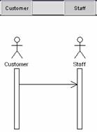
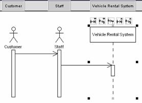
4. Double-click the newly created actor and rename it as ��Staff��. Press Ctrl + Enter to finish the operation. Press the Object Resource icon, and then drag to the right side and release the mouse button to create a new object. Rename the newly created object as ��Vehicle Rental System��.
|
|
è |
|
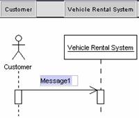
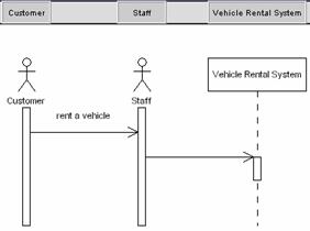
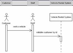
5. Double click on the Customer to Staff message. A textfield appears, input ��rent a vehicle��.
|
|
è |
|
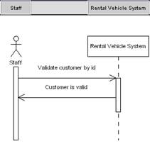
6. Double click on the Staff to Vehicle message. A textfield appears, input ��validate customer by id��.
|
|
è |
|
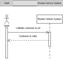
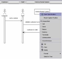
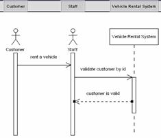
7. Create a message form ��Vehicle Rental System�� to�� Staff��. Rename the
newly created message as ��customer is valid��.
|
|
è |
|


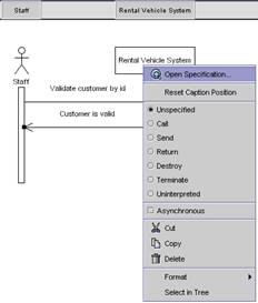
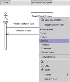
8. Right click on the ��customer is valid�� message. A popup menu appears. Select ��return�� to change the message type.
|
|
è |
|
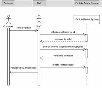
9. According to the above steps, create the following messages :
|
Direction |
Message name |
Message type |
|
From Staff to Vehicle Rental System |
search vehicle based on the customer criteria |
send |
|
From Vehicle Rental System to Staff |
vehicle is available |
return |
|
From Staff to Vehicle Rental System |
create rental record |
send |
|
From Staff to Customer |
vehicle��s key and receipt |
return |
10. The completed diagram will look like the following.
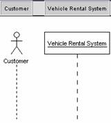
Draw the following diagram according to the guidelines given in this chapter.
![]() Figure 2.6 Sequence Diagram Exercise
Figure 2.6 Sequence Diagram Exercise