State Diagram
A state diagram provides a very detailed
picture of how a specific symbol changes states. A state refers to the value
associated with a specific attribute of an object and to any actions or side
effects that occur when the attribute��s value changes.
![]() Figure 8.1
Figure 8.1
We use state diagram when working on real-time process control applications or systems that involve concurrent processing. It will also be used when showing the behavior of a class over several use cases.
Method 1 �V Creating a State Diagram
using the Menu Bar
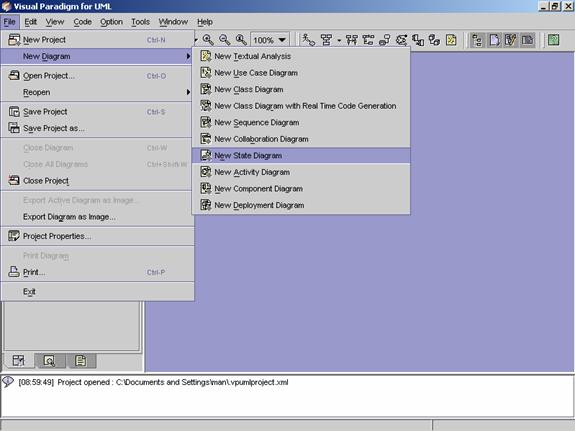
1. Click on File on the menu bar. The file menu appears.
2. Click on New Diagram on the file menu. A cascading menu appears.
3. Click on New State Diagram on the cascading menu. A blank new state diagram appears.
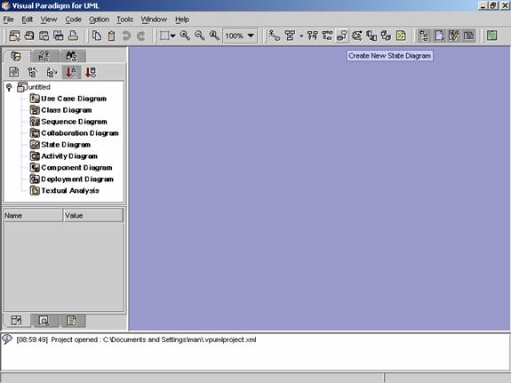
Method 2 �V Creating a State Diagram using the Toolbar
1.
Click on Create
State Diagram ![]() in the toolbar. A blank new state diagram
appears.
in the toolbar. A blank new state diagram
appears.
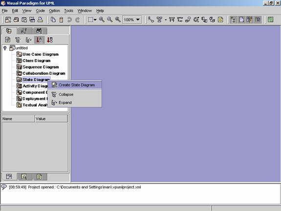
Method 3 �V Creating a State Diagram using the
Project Explorer
1. Right click on Create State Diagram directory in the Project Explorer. A pop-up menu appears.
2. Click on Create State Diagram. A blank new state diagram appears.
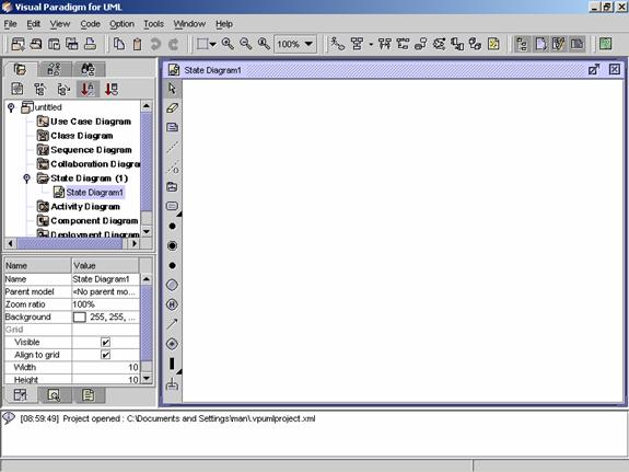
![]() Figure 8.2 A blank new state diagram is created.
Figure 8.2 A blank new state diagram is created.
|
|
Icon |
Notation |
Definition |
|
|
Note |
A note is used for comments additional
explanation, specification and requirement in a diagram element or at a link
in the diagram. It is not
included in generated code. The
contents of a note do not alter the meaning of the model to which it is
attached. A note can contain any combination of text and graphics. It can
also be used in defining a stereotype and entering a noted element. (adapted
from UMLUG-purple) |
|
|
|
Anchor |
An anchor is to line a diagram element and
a note. |
|
|
|
Constraint |
A constraint is a semantic condition or restriction on model elements
that must be enforced by a correct design of a system. It is represented as a linguistic, enclosed in
braces ({}), statement in some formal (OCL, C++, and other), or natural language. There are 14 standard
constraints in the UML such as association, global, parameter. You may also define your own
constraints. |
|
|
|
Subsystem |
A subsystem groups use cases or packages
together. |
|
|
|
State |
A state is a condition or situation in the
life of an object during which it performs some activities, satisfies some
conditions or waits for some events. An object is not always in the same
state at a given time. However, an object cannot be in undefined/unknown
state |
|
|
|
|
A concurrent state (also known as a
concurrent composite state) is divided into two or more substates (called
regions). It is a state that contains other state vertices (states,
pseudostates, etc.). Naturally, any substate of a concurrent state may also
be a composite state of either type. Any state enclosed within a composite
state is called a substate of that concurrent state. |
|
|
|
|
A submachine state represents the
invocation of a state machine defined elsewhere. The submachine state is depicted as a
normal state with the appropriate ��include�� declaration within its internal
transitions compartment. As an option, the submachine state may contain one or
more stub states, which represent already created
states. |
|
|
|
|
A call state is an action state that has
exactly one call action as its entry action. It is useful in object flow
modeling to reduce notational ambiguity over which action is taking input or
providing output. |
|
|
|
|
An action state is a shorthand for a
state with an entry action and at least one outgoing transition involving the
implicit event of completing the entry action (there may be several such
transitions if they have guard conditions). Action states should not have
internal transitions, outgoing transitions based on explicit events, or exit
actions, use normal states for this situation. Transitions leaving an action
state should not include an event signature. Such transitions are implicitly
triggered by the completion of the action in the state. The transitions may
include guard conditions and actions. The normal use of an action state is to
model a step in the execution of an algorithm (a procedure) or a workflow process. |
|
|
|
|
A pseudo state to establish the start of
the event into an actual state. |
|
|
|
|
The final state symbol represents the
completion of the activity. |
|
|
|
Junction Point |
Junction point (see Figure 29 -- Junction point) is used for joining
and splitting transition paths. Regardless of whether the junction point was reached from state State
0 or from state State1, the outgoing paths are the same for both cases. If the state machine in
this example is in state State1 and b is less than 0 when event e1 occurs, the outgoing transition will be
taken only if one of the three downstream guards is true. Thus, if a is equal to 6 at that point, no
transition will be triggered. |
|
|
|
State dynamic choice point |
In the dynamic choice point (see Figure 30 -- Dynamic choice point), a
decision on which branch to take is only made after the transition from State1 is taken and the choice
point is reached. Note that the action associated with that incoming transition computes a new value. This
new value can then be used to determine the outgoing transition to be taken. |
|
|
|
|
History state is a state machine describes
the dynamic aspects of an object whose current behavior depends on its past.
It allows a sequential composite state to remember the last substate that was
active in it prior to a transition from the composite state. If transition to
this state is activated, the object resumes the state it last had. |
|
|
|
Transition |
A transition is a relationship between two
states. This transition indicates that control is passed from the one state
to another state once the condition of the source state is satisfied. To
emphasize functional flow of control, transitions can be labeled, and can
contain parameters, guard conditions and action expressions. |
|
|
|
Synch state |
A synch state is a special state that
enables synchronization of control between two concurrent regions in a state
machine. |
|
|
|
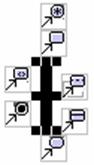
Vertical synchronization |
This merge branch bar symbol is
also known as a ��Synchronization Bar��.
It merges concurrent transitions to a single target. It splits a
single transition into parallel transitions. |
|
|
|
|
Horizontal Synchronization |
This merge branch bar symbol is
also known as a ��Synchronization Bar��.
It merges concurrent transitions to a single target. It splits a
single transition into parallel transitions. |
|
|
|
|
A stub state can appear within a
submachine state and represents an actual subvertex contained within the referenced
state machine. It can serve as a source or destination of transitions that connect a state
vertex in the containing state machine with a subvertex in the referenced state machine. StubState is a child of State. |
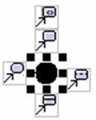
![]() Table 8.1 The State Diagram Palette of VPUML
Table 8.1 The State Diagram Palette of VPUML
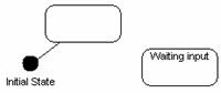
Creating an
Initial State
Method
1 �V Creating an initial state using the diagram palette
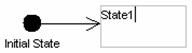
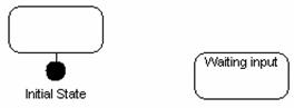
1.
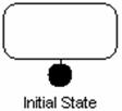
To create an initial state in
your state diagram, click on the initial State button ![]() on the diagram palette and click on the
desired location. A new initial state is created.
on the diagram palette and click on the
desired location. A new initial state is created.
![]()
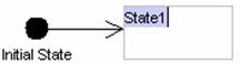
2. Rename the newly created initial state name. Press Ctrl + Enter to finish the operation.
|
|
è |
|


3. The initial state name is set.

Method
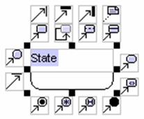
1 �V Creating a state using the diagram palette
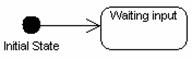
1.
Click State button ![]() on the diagram palette and click on the
desired location. A new state is created.
on the diagram palette and click on the
desired location. A new state is created.
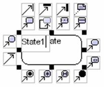
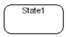
2. Rename the newly created state. Press Ctrl + Enter to finish the operation.
|
|
è |
|
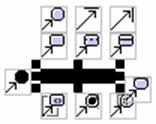
Method 2 �V Creating a state using the resource
centric approach
Diagram elements that a state can be created from, using the resource centric interface are:
l
State ![]()
l
![]()
l
![]()
l
![]()
l
![]()
l
![]()
l
Junction Point ![]()
l
State Dynamic Choice Point ![]()
l
![]()
l
![]()
l
Vertical Synchronization Bar ![]()
l
Horizontal Synchronization Bar ![]()
l
![]()
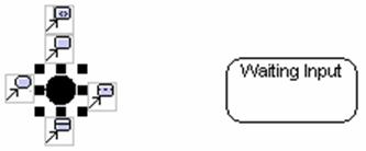
1. Click on an existing initial state. The resource icons appear around the diagram element.
|
|
è |
|
2.
Press on the mouse button on
the State icon ![]() . A new state appears.
. A new state appears.
3. Drag the state to the desired location.
|
|
è |
|
4. Rename the newly created state, and press Ctrl + Enter to finish the operation.
|
|
è |
|
Creating a
Concurrent State
Method
1 �V Creating a concurrent state using the diagram palette
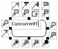
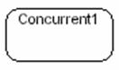
1.
Click Concurrent State button ![]() on the diagram palette and click on the
desired location. A new concurrent state is created.
on the diagram palette and click on the
desired location. A new concurrent state is created.

2. Rename the newly created concurrent state. Press Ctrl + Enter to finish the operation.
|
|
è |
|
Method 2 �V Creating a concurrent state using the
resource centric approach
Diagram elements that a concurrent state can be created from, using the resource centric interface are:
l
State ![]()
l
![]()
l
![]()
l
![]()
l
![]()
l
![]()
l
Junction Point ![]()
l
State Dynamic Choice Point ![]()
l
![]()
l
![]()
l
Vertical Synchronization Bar ![]()
l
Horizontal Synchronization Bar ![]()
l
![]()
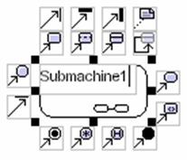
Creating a
Submachine State
Method
1 �V Creating a submachine state using the diagram palette
1.
Click submachine State button ![]() on the diagram palette and click on the
desired location. A new submachine state is created.
on the diagram palette and click on the
desired location. A new submachine state is created.
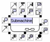
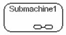
2. Rename the newly created submachine state. Press Ctrl + Enter to finish the operation.
|
|
è |
|
Method 2 �V Creating a submachine state using the
resource centric approach
Diagram elements that a concurrent state can be created from, using the resource centric interface are:
l
State ![]()
l
![]()
l
![]()
l
![]()
l
![]()
l
![]()
l
Junction Point ![]()
l
State Dynamic Choice Point ![]()
l
![]()
l
![]()
l
Vertical Synchronization Bar ![]()
l
Horizontal Synchronization Bar ![]()
l
![]()
Creating a
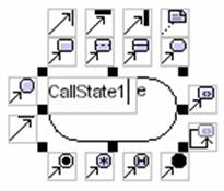
Call State
Method
1 �V Creating a call state using the diagram palette
1.
Click call State button ![]() on the diagram palette and click on the
desired location. A new call state is created.
on the diagram palette and click on the
desired location. A new call state is created.
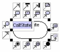
2. Rename the newly created call state. Press Ctrl + Enter to finish the operation.
|
|
è |
|
Method 2 �V Creating a call state using the resource
centric approach
Diagram elements that a call state can be created from, using the resource centric interface are:
l
State ![]()
l
![]()
l
![]()
l
![]()
l
![]()
l
![]()
l
Junction Point ![]()
l
State Dynamic Choice Point ![]()
l
![]()
l
![]()
l
Vertical Synchronization Bar ![]()
l
Horizontal Synchronization Bar ![]()
l
![]()
Creating an
Action State
Method
1 �V Creating an action state using the diagram palette
1.
Click action state button ![]() on the diagram palette and click on the
desired location. A new action state is created.
on the diagram palette and click on the
desired location. A new action state is created.
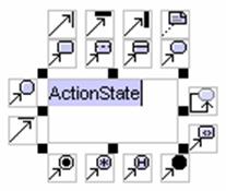
2. Rename the newly created action state. Press Ctrl + Enter to finish the operation.
|
|
è |
|
Method 2 �V Creating an action state using the resource
centric approach
Diagram elements that an action state can be created from, using the resource centric interface are:
l
State ![]()
l
![]()
l
![]()
l
![]()
l
![]()
l
![]()
l
Junction Point ![]()
l
State Dynamic Choice Point ![]()
l
![]()
l
![]()
l
Vertical Synchronization Bar ![]()
l
Horizontal Synchronization Bar ![]()
l
![]()
Method
1 �V Creating a Junction Point using the diagram palette
1.
Creating a junction point in
your state diagram, click on the Junction Point icon ![]() on the diagram palette and click to the
desired location. A new junction point appears.
on the diagram palette and click to the
desired location. A new junction point appears.
![]()
2. Rename the newly created junction point name. Press Ctrl + Enter to finish the operation.
|
|
è |
|

3. The junction point name is set.

Method 2 �V Creating a junction point using the
resource centric interface
Diagram elements that a junction can be created from, using the resource centric interface are:
l
State ![]()
l
![]()
l
![]()
l
![]()
l
![]()
l
![]()
l
Junction Point ![]()
l
State Dynamic Choice Point ![]()
l
![]()
l
![]()
l
Vertical Synchronization Bar ![]()
l
Horizontal Synchronization Bar ![]()
l
![]()
Method
1 �V Creating a state dynamic choice point using the diagram palette
1.
To create a state dynamic
choice point in your state diagram, click on the State Dynamic Choice Point button ![]() on the diagram palette and click on the
desired location. A new state dynamic choice point is created.
on the diagram palette and click on the
desired location. A new state dynamic choice point is created.
![]()
2. Rename the newly created state dynamic choice point name. Press Ctrl + Enter to finish the operation.
|
|
è |
|
3. The state dynamic choice point name is set.
Method 2 �V Creating a State Dynamic Choice Point
using the resource centric interface
Diagram elements that a state dynamic choice point can be created from, using the resource centric interface are:
l
State ![]()
l
![]()
l
![]()
l
![]()
l
![]()
l
![]()
l
Junction Point ![]()
l
State Dynamic Choice Point ![]()
l
![]()
l
![]()
l
Vertical Synchronization Bar ![]()
l
Horizontal Synchronization Bar ![]()
l
![]()
Creating a
History State
Method
1 �V Creating a
1.
To create a history state in
your state diagram, click on the ![]() on the diagram palette and click to the
desired location. A history state is created.
on the diagram palette and click to the
desired location. A history state is created.
![]()
2. Rename the newly created history state name. Press Ctrl + Enter to set the history state name.
|
|
è |
|
3. The history state name is set.

Method 2 �V Creating a
Diagram elements that a history can be created from, using the resource centric interface are:
l
State ![]()
l
![]()
l
![]()
l
![]()
l
![]()
l
![]()
l
State Dynamic Choice Point ![]()
Method
1 �V Creating a transition using the diagram palette
You can create transition between diagram elements listed below in the state diagram.
l
![]()
l
State ![]()
l
![]()
l
Junction Point ![]()
l
Dynamic Point ![]()
l
![]()
l
Vertical Synchronization Bar ![]()
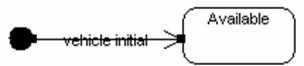
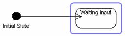
1.
To create a transition in your
state diagram, click on the transition icon ![]() on the diagram palette and click on the
source diagram element.
on the diagram palette and click on the
source diagram element.

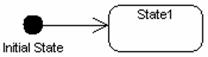
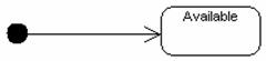
2. Then drag to the target diagram element.
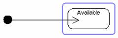
3. A transition is created between the initial state and state.
4. Right click the transition, a pop-up menu is displayed.
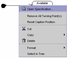
5. The transition specification dialog box is displayed.
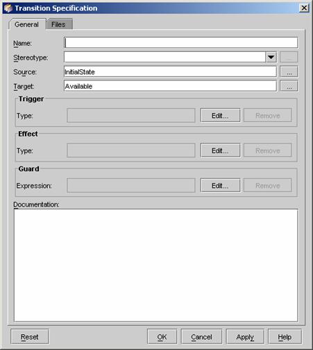
6. Enter ��vehicle initial�� in the Name field.

7. Click OK to close the transition specification dialog box.
8. Move the transition name to appropriate location.
Method 2 �V Creating a transition using the resource
centric interface
Diagram elements that a transition can be created from, using the resource centric interface are:
l
![]()
l
State ![]()
l
Junction Point ![]()
l
Dynamic Point ![]()
l
![]()
l
Vertical Synchronization Bar ![]()
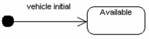
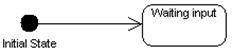
1. Click on the initial state. The resource icons appear.
2.
Press on the mouse button on
the include icon![]() .
A new state appears.
.
A new state appears.
3. Drag the new state to the desired location. Release the mouse button.
|
|
è |
|
4. A transition is created between the initial state and state.
Method
1 �V Creating a Synch state using the diagram palette
1.
To create a synch state in your
state diagram, click on the synch state button ![]() on the diagram palette and click to the
desired location. A new synch state appears.
on the diagram palette and click to the
desired location. A new synch state appears.
![]()
2. Rename the newly created synch state name. Press Ctrl + Enter to finish the operation.
|
|
è |
|

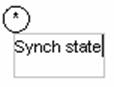
3. The synch state name is set.

Method 2 �V Creating a
Diagram elements that a synch state can be created from, using the resource centric interface are:
l
![]()
l
Junction Point ![]()
l
Dynamic Point ![]()
l
![]()
l
Vertical Synchronization Bar ![]()
Method
1 �V Creating a vertical synchronization bar using the diagram palette
1.
Creating a vertical
synchronization bar in your state diagram, click the vertical synchronization
bar icon ![]() on
the diagram palette and click to the desired location. A new vertical
synchronization appears.
on
the diagram palette and click to the desired location. A new vertical
synchronization appears.
2. Rename the newly created vertical synchronization name. Press Ctrl + Enter to finish the operation.
|
|
è |
|
3. The vertical synchronization name is set.

Method 2 �V Creating a vertical synchronization
bar using the resource centric interface
Diagram elements that a vertical synchronization can be created from, using the resource centric interface are:
l
State ![]()
l
![]()
l
![]()
l
![]()
l
![]()
l
![]()
l
Junction Point ![]()
l
State Dynamic Choice Point ![]()
l
![]()
l
![]()
l
Vertical Synchronization Bar ![]()
l
Horizontal Synchronization Bar ![]()
l
![]()
Method
1 �V Creating a horizontal synchronization bar using the diagram palette
1.
Creating a horizontal synchronization
bar in your state diagram, click the horizontal synchronization bar icon ![]() on the diagram palette and click to the
desired location. A new horizontal synchronization appears.
on the diagram palette and click to the
desired location. A new horizontal synchronization appears.
2. Rename the newly created horizontal synchronization name. Press Ctrl + Enter to finish the operation.
|
|
è |
|
3. The horizontal synchronization name is set.
Method 2 �V Creating a horizontal synchronization
bar using the resource centric interface
Diagram elements that a horizontal synchronization can be created from, using the resource centric interface are:
l
State ![]()
l
![]()
l
![]()
l
![]()
l
![]()
l
![]()
l
Junction Point ![]()
l
State Dynamic Choice Point ![]()
l
![]()
l
![]()
l
Vertical Synchronization Bar ![]()
l
Horizontal Synchronization Bar ![]()
l
![]()
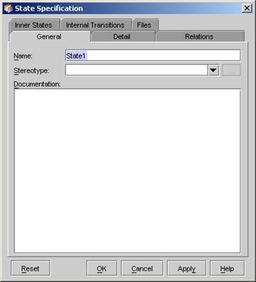
You can edit the specification of a state.
1. Right click on the state that you want to edit. A pop-up menu appears.
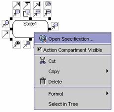
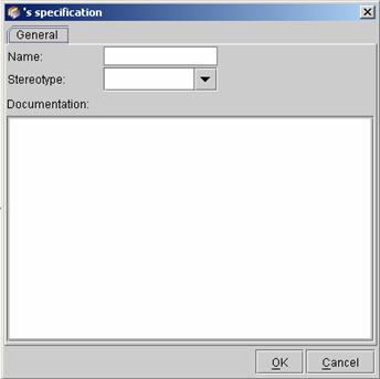
2. Click on Open Specification. A state specification dialog box appears. The name and other related information in the General tab can be modified in the state specification.
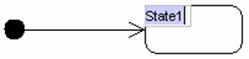
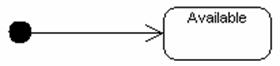
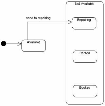
1.
Click on the initial state
button ![]() on the toolbar, and then click to the
desired location. A new initial state appears.
on the toolbar, and then click to the
desired location. A new initial state appears.
![]()
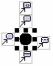
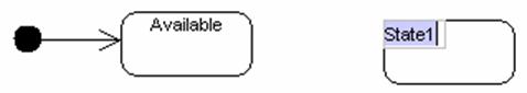
2. Select the newly created initial state, the resource centric is displayed. Then click on state icon and drag to the desired location.
|
|
è |
|
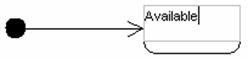
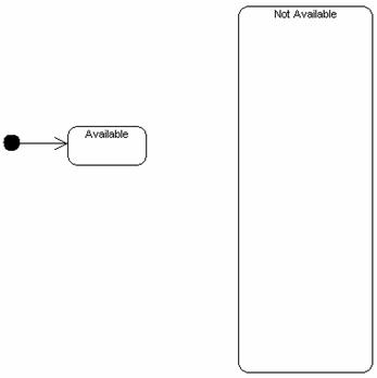
3. Rename the newly created state as ��Available��.
|
|
è |
|
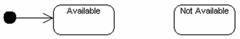
4. Click the state button on the tool bar to create one more state.
5. Rename the newly created state as ��Not Available��.
6. Select the Not Available state, and then select the resize box.
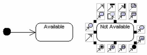
7. Drag it to make the size of ��Not Available�� state larger.
8. Click on the state button on the toolbar, and then click inside the ��Not Available�� state.
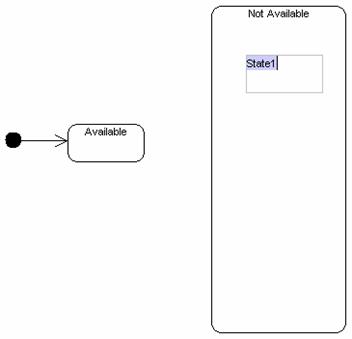
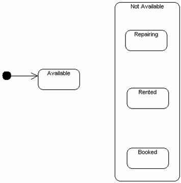
9. Rename the newly created state as ��Repairing��.
10. Then create two more states inside the ��Not Available state�� and rename them as ��Rented�� and ��Booked�� respectively.
11.
Select the ��Available�� state,
and then press on the state icon on the resource centric. 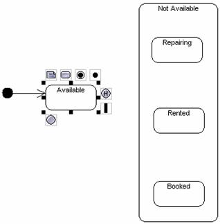
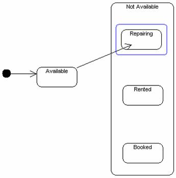
12. Drag to the ��Repairing�� state to create a transition.
13. Press on the new transition.
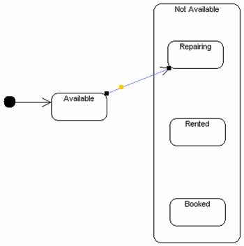
14. Drag it to the appropriate location.
15. Right click on the transition. A pop-up menu appears.
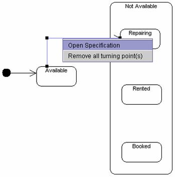
16. Click on Open Specification. The transition specification dialog box appears.
17. Enter ��send to repairing�� in the Name field and click OK.
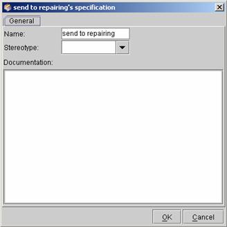
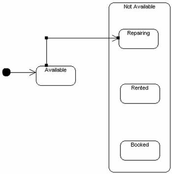
18. The transition name is displayed on the diagram.
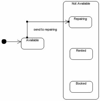
19. Drag the transition name to appropriate location.
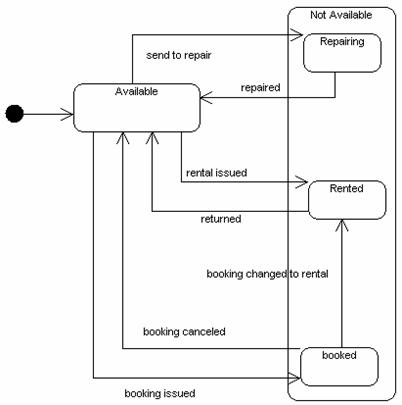
20. According to above method, follow the table below to create more transitions on the diagram, and adjust the transitions and transition names to appropriate locations.
|
From |
To |
Name |
|
Repairing |
Available |
repaired |
|
Available |
Rented |
rental
issued |
|
Rented |
Available |
returned |
|
Available |
Booked |
booking
issued |
|
Booked |
Available |
booking
cancelled |
|
Booked |
Rented |
booking
change to rental |
21. The completed diagram will look as follow.
Draw the below diagram according to the guidelines given in this chapter.
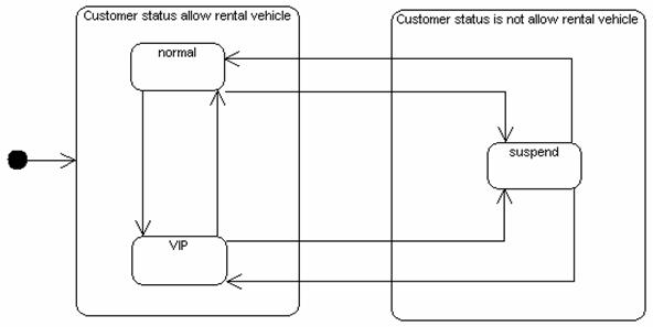
![]() Figure 8.3 Exercise state diagram.
Figure 8.3 Exercise state diagram.