Use
Case Diagram
A Use Case Diagram is a diagram that help system analyst to discover the requirements of the target system from the user's perspective.
l
Describes the behavior of a
system from a user��s standpoint
l
Provides functional description
of a system and its major processes
l
Provides graphic description of
the users of a system and what kinds of interactions to expect within that
system
l
Displays the details of the processes
that occur within the application area
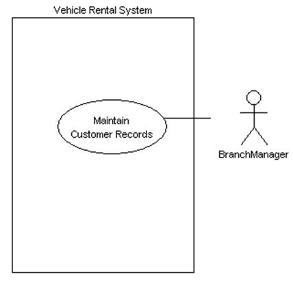
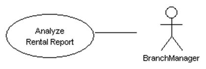
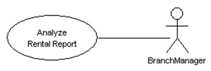
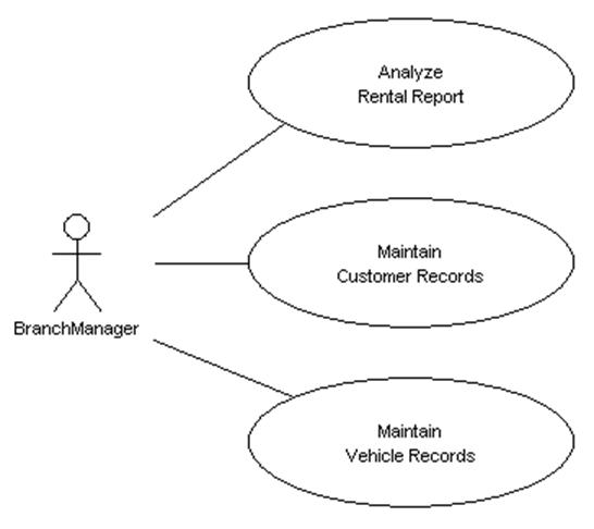
![]() Figure 4.1
A use case diagram
Figure 4.1
A use case diagram
We have to use Use Case Diagram when
describing the requirements for a system in the analysis, design,
implementation and documentation stages.
Method
1 �V Creating a blank new use case diagram using the main menu
1.
Click on File on
the main menu. The file menu appears.
2.
Click on New Diagram on the file menu. A cascading menu appears.
3.
Click on New Use Case Diagram on the cascading menu. A blank new Use Case Diagram appears.

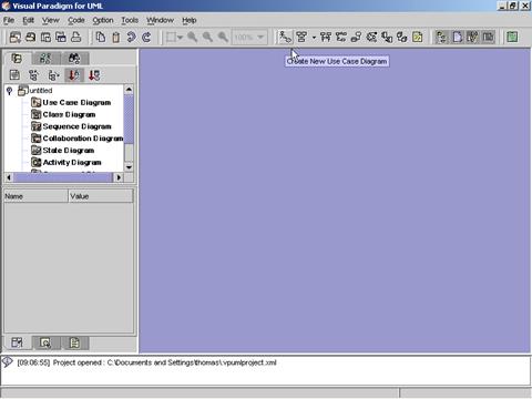
Method
2 �V Creating a blank new use case diagram using the toolbar
1. Click on the Create Use Case Diagram button ![]() on the toolbar. A blank new use case
diagram appears.
on the toolbar. A blank new use case
diagram appears.
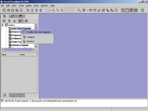
Method
3 �V Creating a blank new use case diagram using the Project Explorer
1.
Right click on the Use Case
Diagram directory in the Project Explorer. A pop-up menu appears.
2.
Click on the Create Use Case Diagram. A blank new use case diagram appears.
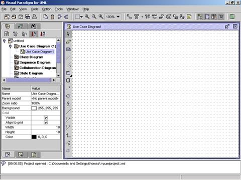
![]() Figure 4.2 A blank new use case diagram is
created.
Figure 4.2 A blank new use case diagram is
created.
|
|
Icon |
Notation |
Definition |
|
|
Note |
The note notation is available on all
diagram palettes. A note can be
used for commenting additional explanation, specification and requirement in
a diagram element or at a link in the diagram. It is not included in generated
code. The contents of a note do
not alter the meaning of the model to which it is attached. A note can
contain any combination of text and graphics. It can also be used in defining
a stereotype and entering a noted element. (adapted from UMLUG-purple) |
|
|
|
Anchor |
The anchor notation is available on all
diagram palettes. An anchor is used to line a diagram element and a note. |
|
|
|
Constraint |
|
|
|
|
Package |
Package is a mechanism for organizing
elements into groups. It is used
in the Use Case, Class, and Component diagrams. Packages may be nested within other
packages. A package may contain both subordinate packages and ordinary model
elements. The entire system
description can be thought of as a single high-level subsystem package with
everything else in it. |
|
|
|
Subsystem |
A subsystem groups diagram elements
together. |
|
|
|
System |
A system/system boundary groups use cases
together to accomplish a purpose. Each use case diagram can only have one
system. |
|
|
|
Dependency |
The dependency link is a semantic
relationship between the two elements. It indicates that when a change occurs
in one element, there may be a change necessary to the other element. A dependency link can include label
and stereotype can be set. |
|
|
|
Use
Case |
Use case describes the behavior of a
system. It is used to structure
things in a model. It contains
multiple scenarios, each of which describes a sequence of actions that is
clear enough for outsiders to understand. (adapted from UMLUG-p) |
|
|
|
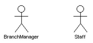
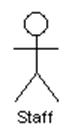
Actor |
An actor represents a coherent set of roles
that users of a system play when interacting with the use cases of the
system. An actor participates in
use cases to accomplish an overall purpose. An actor can represent the role of a
human, a device, or any other systems. |
|
|
|
Association |
Association is used to associate an actor
to a use case. It shows participation of an actor in a use case. It is a set
of links in which a link is a connection among objects. |
|
|
|
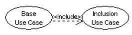
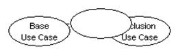
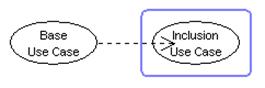
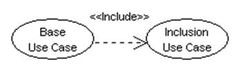
Include |
Include is a link that links an inclusion
use case with a base use case. |
|
|
|
Extend |
Extend is a link that links an extension
use case with a base use case. Extension use case exents the behaviour of the
base use case. |
|
|
|
Generalization |
Generalization is a relationship between a
general element and a more specific kind of that element. It means that the
more specific element can be used whenever the general element appears. This
relation is also known as specialization or inheritance link. |
|
|
|
Realization |
|
|
|
|
Collaboration |
|
![]() Table 2 The Use Case Diagram Palette of VPUML
Table 2 The Use Case Diagram Palette of VPUML
Method
1 �V Creating a use case using the Use Case Diagram Palette
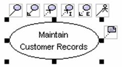
1.
Click on the Use Case button ![]() on the Use Case Diagram Palette. Click on
the desired location on the diagram. A new use case appears.
on the Use Case Diagram Palette. Click on
the desired location on the diagram. A new use case appears.
2. Rename the newly created use case. Press Ctrl + Enter to finish the operation.
|
|
è |
|
Method
2 �V Creating a use case using the resource centric interface
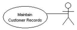
1.
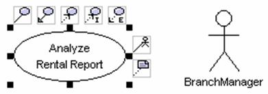
Click on an existing actor on
the diagram. Resource icons appear around the actor.
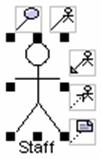
2.
Press on the Association -> Use Case resource icon![]() .
A new use case appears.
.
A new use case appears.
3. Drag the use case to the desired location. Release the mouse button.
|
|
è |
|
4. Rename the newly created use case. Press Ctrl + Enter to finish the operation.
|
|
è |
|
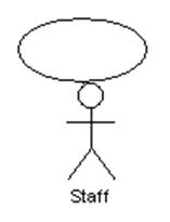
Method
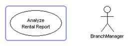
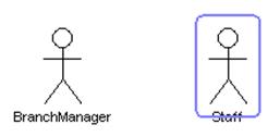
1 �V Creating an actor using the Use Case Diagram Palette
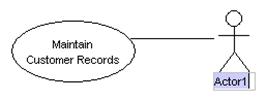
1.
Click on the Actor button ![]() on the Use Case Diagram Palette. Click on
the desired location on the diagram. A new actor appears.
on the Use Case Diagram Palette. Click on
the desired location on the diagram. A new actor appears.
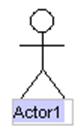
2. Rename the newly created actor. Press Ctrl + Enter to finish the operation.
|
|
è |
|

Method
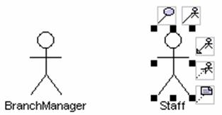
2 �V Creating an actor using the resource centric interface
1.
Click on an existing use case
on the diagram. Resource icons appear around the use case.
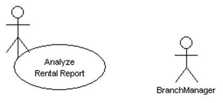
2.
Press on the Association -> Actor resource icon![]() .
A new actor appears.
.
A new actor appears.

3. Drag the actor to the desired location. Release the mouse button.
|
|
è |
|
4. Rename the newly created actor. Press Ctrl + Enter to finish the operation.
|
|
è |
|
You can create one and only one system on a use case diagram.
1.
Click on the System button ![]() on the Use Case Diagram Palette. Click on
the desired location on the diagram. A new system appears.
on the Use Case Diagram Palette. Click on
the desired location on the diagram. A new system appears.
2.
Rename the newly created
system. Press Ctrl + Enter to finish the operation.
ê
3. Click on the use case once so that the system contains the use case.
![]()
It is suggested that a system boundary should be created before creating use cases of the system. If the use cases are created in the system boundary, the system boundary will contain the use cases. If the system boundary does not contain a use case, drag the use case in the system boundary to make the system boundary contains the use case.
Please note that a system boundary will never contain actors.
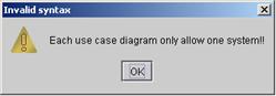
It is not allowed to create more than one system on a use case diagram. A warning dialog box is shown when you try to create more than one system on a use case diagram.
Method
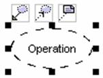
1 �V Creating a collaboration using the Use Case Diagram Palette
1.
Click on the Collaboration button ![]() on the Use Case Diagram Palette. Click on
the desired location on the diagram. A new collaboration appears.
on the Use Case Diagram Palette. Click on
the desired location on the diagram. A new collaboration appears.
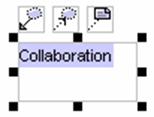
2. Rename the newly created collaboration. Press Ctrl + Enter to finish the operation.
|
|
è |
|
Method
2 �V Creating a collaboration using the resource centric interface
1.
Click on an existing use case
on the diagram. Resource icons appear around the use case.
2.
Press on the Generalization -> Collaboration resource icon![]() .
A new collaboration appears.
.
A new collaboration appears.
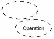
3. Drag the collaboration to the desired location. Release the mouse button.
|
|
è |
|
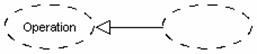
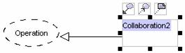
4. Rename the newly created collaboration. Press Ctrl + Enter to finish the operation.
|
|
è |
|
Method
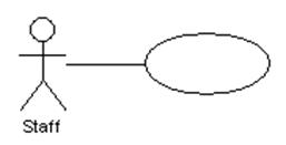
1 �V Creating an association link using the Use Case Diagram Palette
An association relationship can be created between:
l
A use case ![]() and a use case
and a use case ![]() ,
,
l
An actor ![]() and an actor
and an actor ![]() ,
or
,
or
l
An actor ![]() and a use case
and a use case ![]()
1.
Click on the Association button ![]() on the Use Case Diagram Palette. Drag
from either the actor or the use case to the target diagram element.
on the Use Case Diagram Palette. Drag
from either the actor or the use case to the target diagram element.
|
|
è |
|
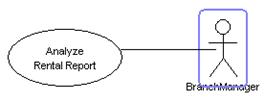
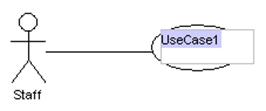
2. Release the mouse button. A new association is created between the diagram elements.
Method
2 �V Creating an association link using the resource centric interface
Diagram elements that an association link can be created from, using the resource centric interface are:
l
Actor ![]()
l
Use Case ![]()
1.
Click on an existing diagram
element listed above on the use case diagram. Resource icons appear around the
diagram element.
2.
Press on the Association -> Use Case resource icon![]() (Note: Click association -> actor resource icon
(Note: Click association -> actor resource icon ![]() for creating association between actors,
or between use case and actor). A new diagram element appears.
for creating association between actors,
or between use case and actor). A new diagram element appears.
3. Drag the new diagram element to the target diagram element. The target diagram element is selected.
|
|
è |
|

4.
Release the mouse button. The
association link is created between the diagram elements.
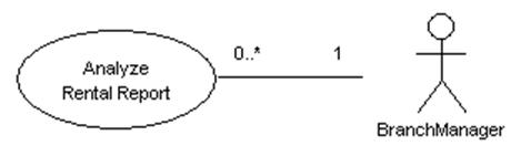
You can define the multiplicity of a role.
1. Right click on an existing association link on the diagram. A pop-up menu appears.
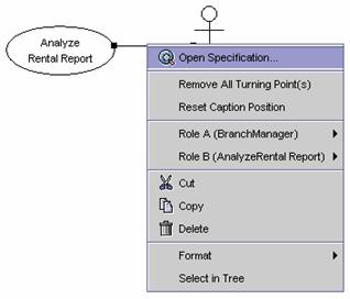
2. Choose the Role A(xxx) on the menu. A cascading menu appears.
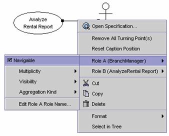
3. Choose the Multiplicity on the menu. A cascading menu appears.

4. Choose one of the multiplicities (0, 0..1, 0..*, 1, 1..*, *, Unspecified, Other�K) on the cascading menu. Then the multiplicity of the role is set.

5. Repeat the above steps to set the display the multiplicity cascading menu for Role B(xxx).
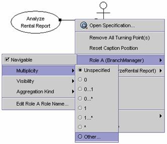
6. Choose Other�K on the menu to specify the multiplicity of the use case. An input dialog box appears.
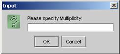
7. Input the multiplicity of the role such as 0..n. The multiplicity of the other role is set.
Method
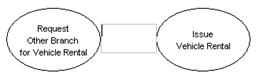
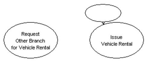
1 �V Creating an <<extend>> relationship link using the Use Case
Diagram Palette

1.
Click on the Extend button ![]() on the Use Case Diagram Palette. Drag
from a use case to the other use case.
on the Use Case Diagram Palette. Drag
from a use case to the other use case.
|
|
è |
|
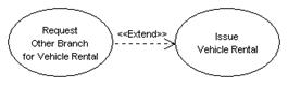
2. Rename the newly created <<extend>> relationship link. Press Ctrl + Enter to finish the operation.
|
|
è |
|
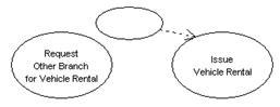
Method
2 �V Creating an <<extend>> relationship link using the resource
centric interface
1.
Click on an existing use case
on the diagram. Resource icons appear around the use case.
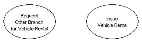
2.
Press on the Extend -> Use Case resource icon![]() .
A new use case appears.
.
A new use case appears.
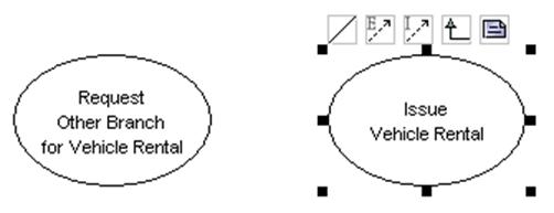
3. Drag the new use case to the target use case. Release the mouse button.
|
|
è |
|
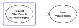
4.
A new <<extend>>
relationship link is created between the use cases.
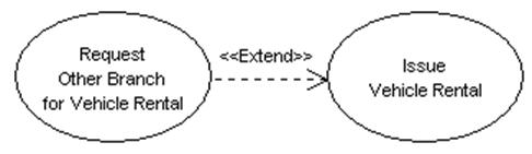
5. Double Click on the <<extend>> relationship link. A text box appears.
6. Rename the <<extend>> relationship link. Press Ctrl + Enter to finish the operation.
|
|
è |
|
7. Drag the <<extend>> relationship name and move it to the desired location.
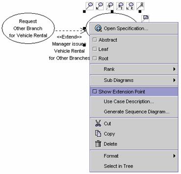
1. Right Click on the base use case. A pop-up menu appears.
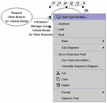
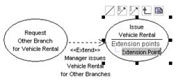
2. Check the Extension Point checkbox. The extension point of the base use case appears.
 =>
=> 
3. Click on the extension point. A text box appears. Rename the extension point. Press Ctrl + Enter to finish the operation.
|
|
è |
|
4. The extension point definition is set.
Method
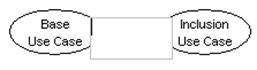
1 �V Creating an <<include>> relationship link using the Use Case
Diagram Palette
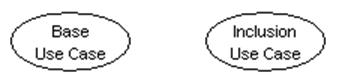
1.
Click on the Include button ![]() on the Use Case Diagram Palette. Drag
from a use case to the other use case.
on the Use Case Diagram Palette. Drag
from a use case to the other use case.
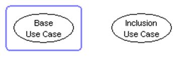

2. Rename the newly created <<include>> relationship link. Press Ctrl + Enter to finish the operation.
|
|
è |
|
Method
2 �V Creating an <<include>> relationship link using the resource
centric interface
1.
Click on an existing use case
on the diagram. Resource icons appear around the use case.
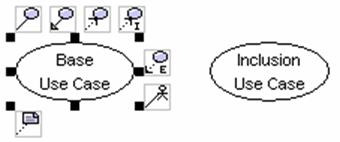
2.
Press on the Include -> Use Case resource icon![]() .
A new use case appears.
.
A new use case appears.
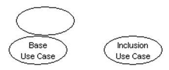
3. Drag the new use case to the target use case.
|
|
è |
|
4.
Release the mouse button. A new
<<include>> relationship link is created between the use cases.
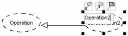
You can create a generalization
relationship link between actors, or between use cases.
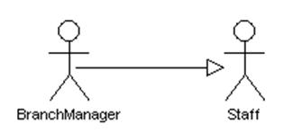
Method
1 �V Creating a generalization relationship link using the Use Case Diagram
Palette
1.
Click on the Generalization Relationship button ![]() on the Use Case Diagram Palette. Drag
from the source diagram element to the target diagram element.
on the Use Case Diagram Palette. Drag
from the source diagram element to the target diagram element.
|
|
è |
|
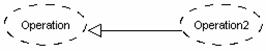
2.
Release the mouse button. A new
generalization relationship link is created between diagram elements.
Method
2 �V Creating a generalization relationship link using the resource centric
interface
1.
Click on an existing diagram
element (actor or use case) on the diagram. Resource icons appear around the
diagram element.
2.
Press on the Generalization resource icon![]() .
A new diagram element appears.
.
A new diagram element appears.
3. Drag the new diagram element to the target diagram element.
|
|
è |
|
4.
Release the mouse button. The
new generalization relationship link is created between the diagram elements.
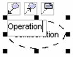
All the properties of a class can be modified using the class specification dialog box.
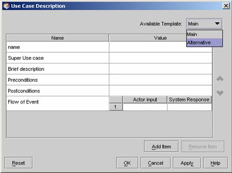
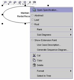
1. Right click on an existing use case on the diagram. A pop-up menu appears.
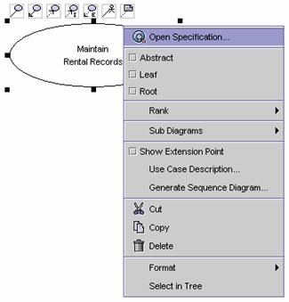
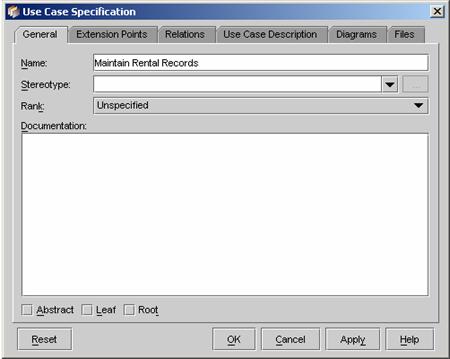
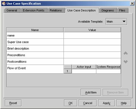
2. Click on Open Specification on the pop-up menu. The Specification dialog box appears. The properties such as name, priority rank, stereotype and so on can be modified in the dialog box.
3. Click on the Use Case Description tag. The use case description of the use case appears. (Read the Editing Use Case Description with a Use Case section for more details.)
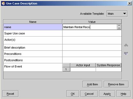
1. Right click on the use case. A popup menu appears.
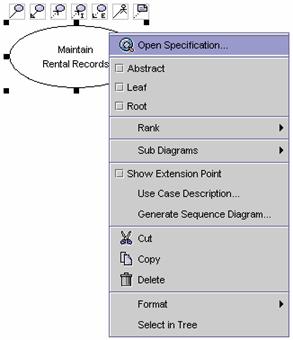
2. Click on the Use Case Description on the popup menu. The use case description of the use case appears.
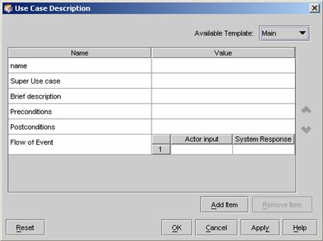
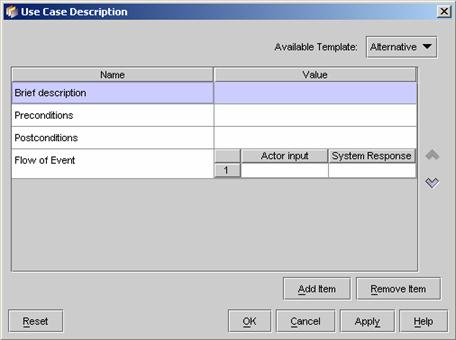
3. To change the template of the use case, click on the Available Template combo box. Select the desired template in the combo box.
4. The template of the use case description is changed. Select the Main template again.
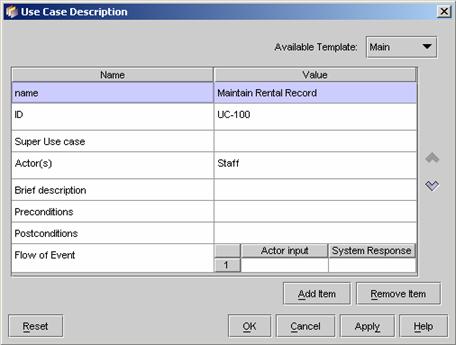
5. To add a new item in the template, click Add Item button in the dialog. An input dialog appears.
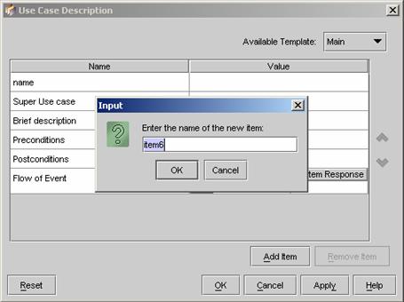
6. Input the item name in the input dialog box. Click OK button to finish the operation.
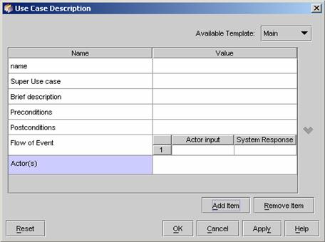
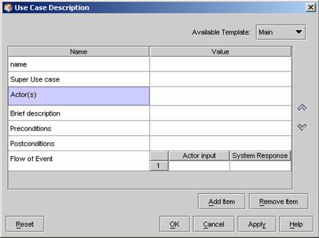
7.
To rearrange the items of the
template, click the Move Up ![]() button and Move Down
button and Move Down ![]() button.
button.
8. Click on the Value column to edit the use case description.
9. To edit the flow of events in the use case description, click on the Value column of the Flow of Event item. Click on the table in the Value column to insert a new Actor Input or System Response.
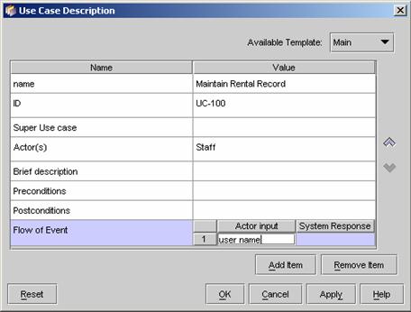
10. After editing a new Actor Input, a new input row will automatically added in the table.
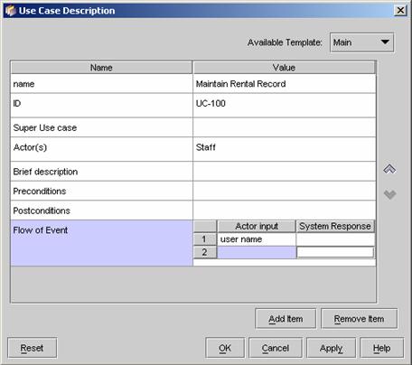
11. Click on the table to adding a new System Response. Then click OK button to finish editing the use case description.

1. Right click on an existing use case. A pop-up menu appears.
2. Click on Sub Diagrams. A cascading menu appears.
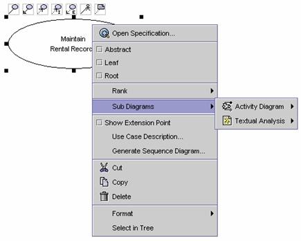
3. Click on Textual Analysis. A cascading menu appears.
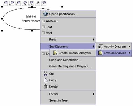
4. Click on the Create Textual Analysis. The textual analysis window appears.
5. Find out the nouns in the problem statement. Drag the candidate classes to the Candidate Class Container. The candidate classes are highlighted. (See Chapter 1 - Textual Analysis for more details)
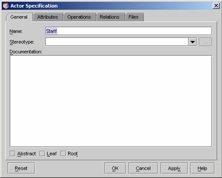
All the properties of an actor can be modified using the specification dialog box.
1. Right click on the actor. A pop-up menu appears.

2. Click on Open Specification. The specification dialog box appears. You can modify the actor��s properties in the specification dialog box.
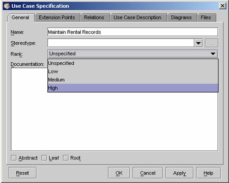
Use cases can be prioritized into 4 categories - Unspecified, Low, Medium and High.
1. Right click on an empty area on the diagram. A pop-up menu appears.
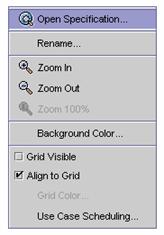
2. Click on Use Case Scheduling on the pop-up menu. The Use Case Scheduling dialog box for the use case diagram appears. It shows a list of use cases on the diagram.
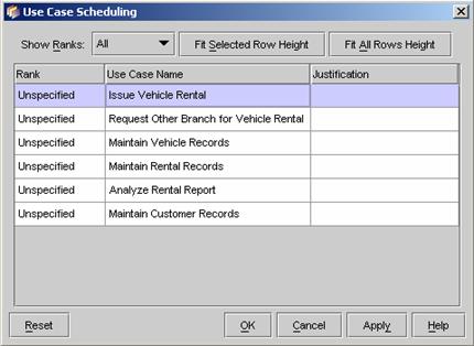
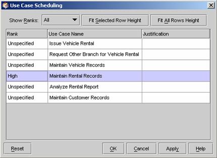
3. Click on a cell in the Rank column of the table. A pull-down box appears.

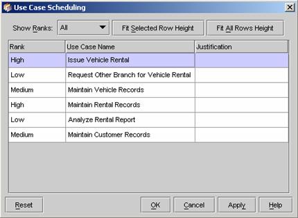
4. Choose one of the priority categories for the use case. Then the priority is set for the use case. Prioritize other use cases in the table.
5. Click on a cell in the Justification column to input the justification for the priority setting.
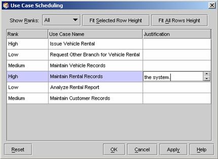
6. Click on the Fit Selected Row Height button to adjust the row height (or click on the Fit All Rows Height to adjust the heights of all the rows).
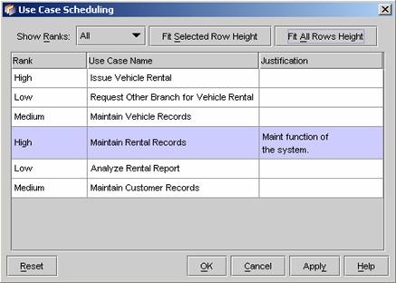
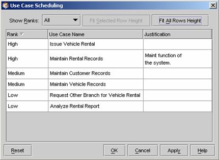
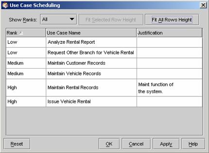
7. Click on the Rank column heading, the use case will be sorted. The use cases can be sorted in either ascending or descending order with the priority ranking.
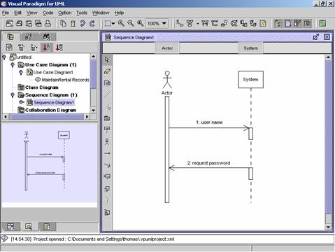
1.
Right click on the use case. A
popup menu appears.
2.
Click Generate Sequence Diagram in the popup menu. A new sequence diagram
(System level) will be generated according to the flow of events defined in the
use case description of the use case.
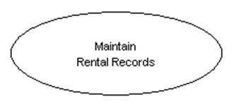
1.
Click on the Use Case button on the Use Case Diagram Palette. Click on an empty area on the use
case diagram. A new use case appears. Rename the use case as ��Maintain Rental
Records��.
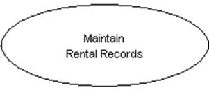
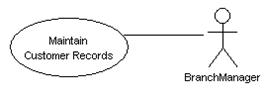
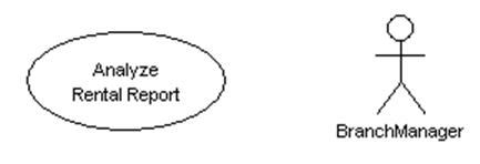
2. Repeat the steps above to create more use cases with the names: Issue Vehicle Rental, Maintain Rental Records, Maintain Vehicle Records and Maintain Customer Records and Analyze Rental Report.
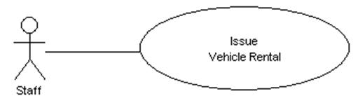
2.
2.
2.
2.Click on the use case named as Issue Vehicle Rental. Resource icons
appear around the use case. Click on the Association -> Actor resource icon. A new actor appears. Drag it to a desired location and rename it
as ��Staff��.
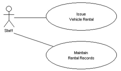
2.
2.
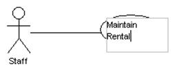
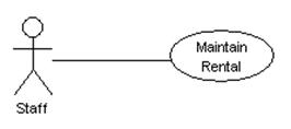
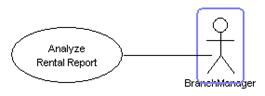
2.Click on the use case named as Maintain Rental Records. Resource
icons appear the use case. Click on the Association -> Actor resource icon. A new actor appears. Drag the new actor to the actor named as Staff.
An association relationship link is created between the actor and the use case.
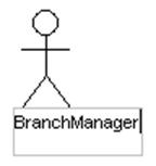
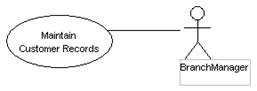
3.
Repeat the steps above to
create a new actor as ��BranchManager�� and create association relationship links
between the actor and the use cases with the names: Maintain Rental Records,
Maintain Customer Records and Analyze Rental Report.
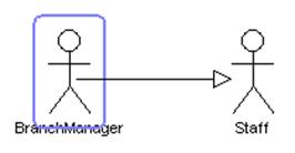
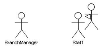
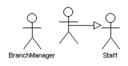
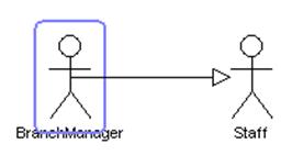
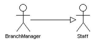
4. Click on the actor named as Staff. Resource icons appear around the actor. Click on the Generalization -> Actor resource icon. A new actor appears. Drag the new actor to the BranchManager actor. The new actor disappears. Then a generalization relationship link is created between the actors.
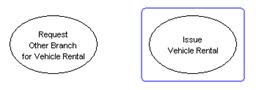
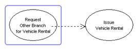
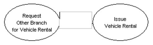
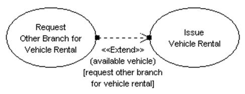
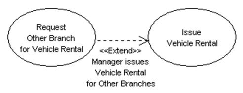
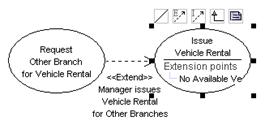
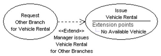
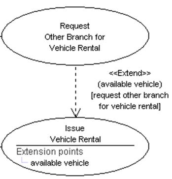
5. Click on the use case Issue Vehicle Rental. Resource icons appear around the use case. Click on the Extend -> Use Case resource icon. A new use case appears. Drag the new use case to the desired location. Rename the use case as ��Request Other Branch for Vehicle Rental��. Then the new use case becomes extension use case.
6. Create an association relationship between the actor named BranchManager and the use case named Request Other Branches for Vehicle Rental. Then rearrange the diagram elements.
7. Right click on the use case named Issue Vehicle Rental. A pop-up menu appears. Check Extension Point on the pop-up menu. The extension point of the use case appears. Click on the extension point. A text box appears. Rename the extension point as ��vehicle available��.
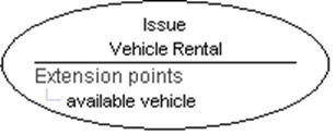
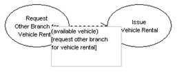
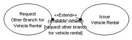
8.
Double-Click on the extension
link. A text box appears. Rename the link as ��(available vehicle) [request
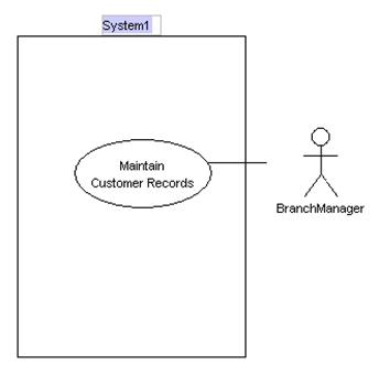
other branch for vehicle rental]��.
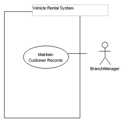
9. Click on the system button on the Use Case Diagram Palette. Click on the use case diagram. A system boundary appears. Rename the system as ��Vehicle Rental System��. Drag the use cases into the system boundary to make the system boundary to contain the use cases.
10. Right click on an empty area on the diagram. A pop-up menu appears. Click Open Specification on the pop-up menu. The use case diagram specification dialog box appears. Click on the Schedule tab. A list of use case is shown.

11. Set the priorities of the use cases and input the justifications for the priorities. Then click OK to exit the dialog box.
|
Use Case |
Priority |
|
Maintain Vehicle Records |
High |
|
Issue Vehicle Rental |
High |
|
Maintain Vehicle Records |
Medium |
|
Maintain Customer Records |
Medium |
|
Request Other Branches for Vehicle Rental |
Low |
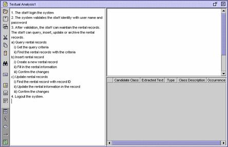
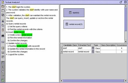
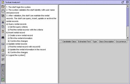
12. Right click on the use case named Maintain Rental Records on the use case diagram. A pop-up menu appears. Click Sub Diagrams. A cascading menu appears. Click Textual Analysis. A cascading menu appears. Click Create Textual Analysis. A blank textual analysis document is opened. Input the following text in the document.
Maintain Rental Records
Flow of events
1. The staff login the system
2. The system validates the staff identity with user name and password
3. After validation, the staff can maintain the rental records. The staff can query, insert, update or archive the rental records.
a) Query rental records
i) Get the query criteria
ii) Find the rental records with the criteria
b) Insert rental record
i) Create a new rental record
ii) Fill in the rental information
iii) Confirm the changes
c) Update rental records
i) Find the rental record with record ID
ii) Update the rental information in the record
iii) Confirm the changes
4. Logout the system.
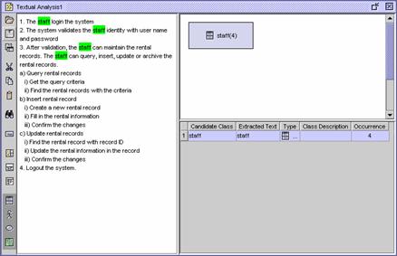
13. Perform textual analysis with the statements. Find out all candidate use case, actor and class in the statements and add them to the Candidate Container. (Read the Textual Analysis tutorial for more details.)
Draw the diagram below according to the guidelines given in this chapter.
![]() Figure 4.3 A use case diagram
Figure 4.3 A use case diagram