
There are two methods to preview your work before printing:
Method 1 – Opening Print
Preview using the menu bar
1.
Click on File on the menu bar. The file menu appears.
2.
Click on Print… on the file menu. The Print Preview pane
appears.
Method 2 – Opening Print
Preview using the toolbar
1.
Click on the Print  button on the toolbar, the Print Preview pane
appears.
button on the toolbar, the Print Preview pane
appears.
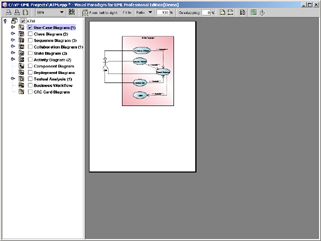
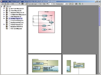
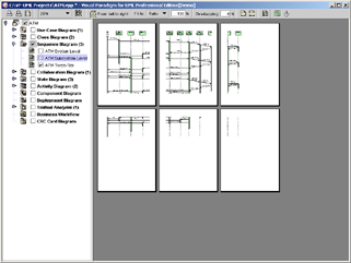
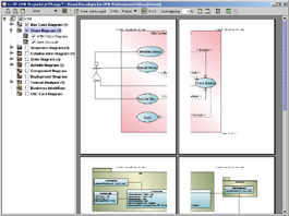
A preview of the diagrams will be appeared as illustrated in the following screen.
The toolbar of the print preview pane allows you to
configure the print settings. The buttons and their descriptions are shown in
the table below:
|

|
|
Icon
|
Button
|
Function
|
|
|
Print
|
Print
the diagram(s). The Print dialog box will be opened.
|
|

|
Page
Setup
|
Set up
the page properties for the diagrams to be printed such as paper size and
orientation.
|
|

|
Adjust
Margins
|
Adjust
the margins of the pages to be printed.
|
|

|
Zoom
|
Select
the percentage to reduce/enlarge the print preview of diagrams.
|
|
 / /
|
Paper
Base Layout/Diagram Base Layout
|
If the
Fit to Pages option is selected, and there are multiple pages in the
printout, selecting Paper Base Layout will cause the distribution of
pages to be paper-oriented (the diagram size is ignored in arranging the
preview); while selecting Diagram Base Layout will cause the
distribution of pages to be diagram-oriented. Note that this option affects
the preview only; the order of the printout remains unchanged.
|
|
|
Paper
Place Style
|
To
change the order of the printout. Consider a large diagram is divided into
many pages, selecting From left to right will arrange the printout
order from the pages on the left to the pages on the right, while selecting From
top to bottom will arrange the print order from the pages on the top to
the pages on the bottom.
|
|

|
Fit to
Ratio
|
Set
the diagram size to fit to the specified ratio.
|
|
|
Fit to
Pages
|
Set
the diagram to be printed on the number of pages specified.
|
|
|
Overlapping
|
Set
the percentage of the margins to overlap among adjacent pages.
|
|

|
Show/Hide
Clip Marks on Page
|
Select/deselect
to show/hide the clip marks on the printout.
|
|

|
Edit
Header/Footer
|
Edit
the header and the footer of the printout.
|
|

|
Multiple
Page Mode
|
Switch
to the Multiple Page Mode to set the multiple page options.
|
|

|
Help
|
Calling
the VP-UML help file
|
|

|
Close
Print Preview
|
Close
the print preview pane and return to the design area.
|
Table 2‑1 The Print Preview toolbar
You can use the Print command to select the printer. Set
the range of pages and number of copies to be printed. The Print command is
available once a project is open.
1.
Select the desired diagrams for printing. The selected diagrams will be
shown at the preview area.
2.
Click on the Print button on the Print Preview Toolbar. The Print
dialog box appears.
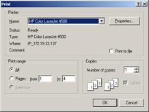
3.
Select the printer to use, the page range and the number of copies to be
printed. You may click on the Properties… button to configure the
printer-specific properties as well.
4.
Click OK to start printing.
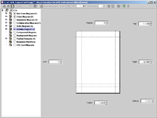
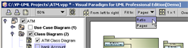
Page Setup allows user to specify
the page size, the orientation as well as the margins of the pages.

1.
Click on the Page Setup button on the toolbar. The Page Setup dialog box
appears.
2.
You can click on the Size pull-down box to select the paper size to use.
3.
You can select the orientation for the page(s) to be printed (either Portrait
or Landscape) in the Orientation field.
4.
You can enter the value into the Left, Right, Top
and Bottom text fields to adjust the size of the corresponding margin.
5.
Click OK to confirm the settings.
The Margins pane allows user to specify the margins of the pages,
header and footer.
1.
Click on the Adjust Margins button on the Toolbar. The preview area shows the margin setting page.
2.
You can edit the margins sizes by entering the sizes into the text
fields. Alternatively, click on the spinner buttons to increase/decrease the
margin sizes.
3.
Click the Finish Adjust Margin button when you have finished configuring the margin
settings. The margin sizes will then be updated.
Diagrams can be zoomed in or zoomed
out according to user preference.
1.
Click on the Zoom pull-down box to select the desired zoom ratio.
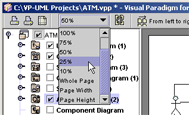
2.
The preview area will show the diagrams in the zoom ratio that you
have selected.
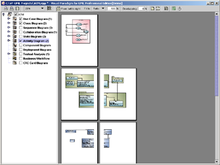
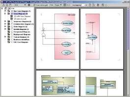
There are two layouts that you can select for the print
preview, the Paper Base Layout and the Diagram Base Layout.
If the Fit to Pages option is selected, and there
are multiple pages in the printout, selecting Paper Base Layout will
cause the distribution of pages to be paper-oriented (the diagram size is
ignored in arranging the preview); while selecting Diagram Base Layout
will cause the distribution of pages to be diagram-oriented.
Note that this option affects the preview only; the order of the printout remains unchanged
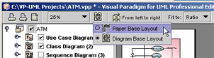
To select a layout of the preview:
1.
Click on the Paper Base Layout button  or Diagram Base Layout button on the toolbar, a popup menu
appears where you can select the layout to use.
or Diagram Base Layout button on the toolbar, a popup menu
appears where you can select the layout to use.
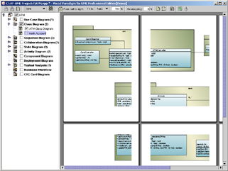
The preview after applying the Paper Base Layout:
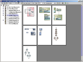
The preview after applying the Diagram Base Layout:
You can select the paper place style to change the order of the printout. To select the paper place style click on the Paper Place Style
button on the toolbar. A popup menu appears where you can select a paper place
style.
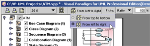
Consider a large diagram is divided into many pages,
selecting From left to right will arrange the printout order from the pages on the left to the pages on the right, while selecting From top
to bottom will arrange the print order from the pages on the top to the
pages on the bottom
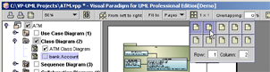
The order of the printout after
selecting From left to right.
Fit to Ratio is used to resize the
diagrams in the printout to a specific ratio.
Click on the Fit to pull-down
box and select Ratio.
You can enter the ratio into the textbox. For example,
enter 150 to set the ratio to 150%. After the have edited the ratio, the
diagrams in the printout will be resized to the new ratio.
Fit to Pages is used to split the
diagram to desired number of pages when printing.
1.
Click on the Fit to pull-down box and select Pages.

2.
Click on the Multiple Pages button  on the toolbar. The page selector appears.
3.
Click on the row-column combination to select it (note that you can click and drag on the page selector to extend the selection). The
diagram will be split into multiple pages by the rows and columns that you have
selected.

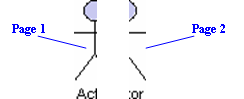
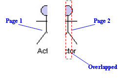
Overlapping is used when users want the diagrams to have
overlapping at the boundaries between pages. This is particularly useful when
you have a large diagram that span multiple pages and you want to stick the
pages of the printout together; the overlapping area can then be used as a hint
when sticking the pages.
1.
Click on the Overlapping textbox to input the overlapping percentage and press the Enter key.
2.
The printing area near the boundaries of the pages will be duplicated by
the overlapping percentage inputted.
Clip marks act as an indication of the boundary of a page.
To show clip marks on the printout click on the Show Clip Marks on Page
button . You will see the
boundaries of the pages are surrounded by clip marks. To
hide the clip marks click on the Hide Clip Marks on Page button again.
To edit the header/footer of the printout click on the Edit
Header/Footer button on
the toolbar. You will then switch to the edit header/footer pane.
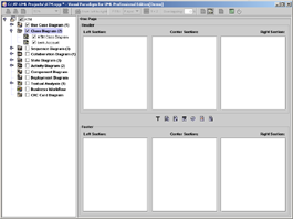
You can edit the header and the footer in the Header panel and the Footer panel respectively. Each of the
panel consists of the Left Section, Center Section and the Right
Section, which represents the position that the content will be located in
the header/footer.
There is a toolbar between the Header panel and the Footer
panel, which facilitates the editing of header/footer. The description of the
buttons in the toolbar can be found in the following table:
|
Icon
|
Name
|
Description
|
|

|
Select
Font
|
Select
the font to use for the selected section. Note that you must click on the
section once in order to select it
|
|

|
Insert
Page Number
|
Insert
the page number in the selected section
|
|

|
Insert
Number of Page
|
Insert
the total number of pages in the selected section
|
|

|
Insert
Date
|
Insert
the date that the printing starts in the selected section
|
|

|
Insert
Time
|
Insert
the time that the printing starts in the selected section
|
|

|
Insert
File Name
|
Insert
the file name of the VP-UML project in the selected section
|
|

|
Insert
Diagram Name
|
Insert
the diagram name in the selected section
|
Table 2‑2 The header/footer toolbar
After you have finished editing the header/footer click on the Close Edit Header/Footer button to switch to the print preview mode. A sample page that has the header and footer formatted is shown in the
picture below:
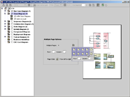
The Multiple Page Mode allows users to configure how the
diagrams should be distributes in multiple pages. To switch to the Multiple
Page Mode click on the Multiple Page Mode button on the toolbar.
Click on the button beside the Multiple Pages field
will invoke the page selector, where you can select the row-column combination
for the printout. Alternatively, you can type in the Row and Column
text field directly.
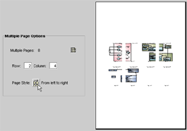
Click on the button beside the Page Style field to
change the printout order. Consider a large diagram is divided into many pages,
selecting From left to right will arrange the printout order from the
pages on the left to the pages on the right, while selecting From top to
bottom will arrange the print order from the pages on the top to the pages
on the bottom.
After you have finished configuring the multiple page
settings click on the Close Multiple Page Mode button to close the
Multiple Page Mode.